Yes, but XLR input circuits with equal impedances have been around for quite some time now. So, I must be able to find a ready designed circuit even on these fora.Something like that would give good rejection. There is one minor disadvantage to a simple circuit like this and that is the input impedance is different for each input. Yours would have a 25k and 50k for each input.
The simple circuit posted should present equal impedances to both the non-inverted and inverted signals with the addition of a single resistor across the higher native impedance.
I added another resistor in parallel with the higher impedance. Now the input currents should be equal implying equal impedances seen by the signal source.
I am attaching the modified circuit.
I added another resistor in parallel with the higher impedance. Now the input currents should be equal implying equal impedances seen by the signal source.
I am attaching the modified circuit.
Attachments
Yes, that extra resistor equalises the currents OK. I guess it all depends how much you want to refine the design... and whether the design actually needs all this... in other words is it to correct a problem in use or is it just refinement.
Now, I am using a mica silver plated capacitor for a Miller compensating capacitor. The value is 100pF, 500V as calculated by LTSpice. Till, now it is seems there are no problems. 😀
Started work on Channel B amplifier. 🙂
Started work on Channel B amplifier. 🙂
Today, I wired up the large autotransformer that will be used for the first high voltage test. The output voltage is 120V ac. So, the unrectified voltage should be: 120*(62.5/230) = 32.6V ac. This will give a rail voltage of approximately: 32.6*sqrt(2) = 46V DC
I will use two 10 Ohm wire wound resistors one on each rail. This is a rail to rail voltage of 92V.
I will use two 10 Ohm wire wound resistors one on each rail. This is a rail to rail voltage of 92V.
First High Voltage Test
Rail to Rail Voltage: 76V DC
Test Duration: 2 minutes approx.
Result:
i) No heat issues.
ii) No signal current drawn remained small. Rail current limiters, 10 Ohm, 5W resistors, remained cool.
Rail to Rail Voltage: 76V DC
Test Duration: 2 minutes approx.
Result:
i) No heat issues.
ii) No signal current drawn remained small. Rail current limiters, 10 Ohm, 5W resistors, remained cool.
Rail to Rail Voltage: 76V DC
Test Duration: 2 minutes approx.
Result:
i) No heat issues.
ii) No signal current drawn remained small. Rail current limiters, 10 Ohm, 5W resistors, remained cool.
A positive first step however you should quantify the voltage drop and see if you can move that down to a minimum and how smooth the adjustment is in that process and then again in restoring the original setting.
A positive first step however you should quantify the voltage drop and see if you can move that down to a minimum and how smooth the adjustment is in that process and then again in restoring the original setting. One assumes the dc offset is not a problem
With the first actual high voltage test passed, the next step is to test for amplifier thermal stability for far longer times. These tests will be done without a signal source. As the amplifier originally used forced cooling, and with the 120V ac source the cooling fan is not functioning, I will need to use an external fan to cool the heatsinks.
The power source will be altered to include an MCB.
Power Source Wiring:
3-pin-mains-plug(UK type)====>autotransformer====>5A MCB====>output-mains-socket
I already have a 10A MCB available. My question is whether a 10A MCB would have sufficiently low trip current in the event of a fault or overcurrent?
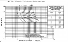
MCB data sheets should show trip time vs overload current, for example a 10A breaker @ 20 amps would take around 2 mins to trip. MCB's are really to protect the infrastructure such as cabling rather than to provide protection for the equipment it supplies.
Attachments
OK, Mooly, I used the good old method of a series filament lamp in place of the MCB. I used two filament lamps with a total power of 160W to get a rail to rail voltage of 72V.
The amplifier passed also this test. I tried the amplifier for a longer time, and seeing that nothing suspicious happened, I shorted the protective lamps. The rail to rail voltage rose to 82V. Since, this test also showed there were no issues, I measured the DC offset voltage at the output before connecting a loudspeaker. The offset voltage was 10mV. Testing the amplifier with a music source and a loudspeaker, I was again pleasantly greeted with good performance.
The amplifier passed also this test. I tried the amplifier for a longer time, and seeing that nothing suspicious happened, I shorted the protective lamps. The rail to rail voltage rose to 82V. Since, this test also showed there were no issues, I measured the DC offset voltage at the output before connecting a loudspeaker. The offset voltage was 10mV. Testing the amplifier with a music source and a loudspeaker, I was again pleasantly greeted with good performance.
It sounds like you have done a great job here  and you have certainly gone about it in a methodical manner. 10mv offset is very tiny in the scheme of things and its not worth looking to reduce it any lower imo.
Excellent 🙂
and you have certainly gone about it in a methodical manner. 10mv offset is very tiny in the scheme of things and its not worth looking to reduce it any lower imo.Excellent 🙂
After installing the amplifier circuit in its box to be used with its intended power supply and testing it, a weak unsteady noise signal could be heard in a connected speaker without an applied signal to the input. Measuring this voltage with a multimeter, I found it flactuates between 1.5mV and 2.1mV. The DC offset at the output also varies slightly with the same pattern and frequency. The DC offset stays between 9mV and 13mV. The noise is audible with a periodicity that varies between 1 and 2 seconds and is continuous.
Possible sources for this instability can be caused by the current sources' bias voltage dropper since this connects directly with the power supply. This is formed by a 10K resistor and two signal diodes in series. My tentative solution is to connect a 2.2uF (electrolytic) and a 2.2nF capacitors in parallel with the two series diodes to shunt any interfering signals from the mains.
Possible sources for this instability can be caused by the current sources' bias voltage dropper since this connects directly with the power supply. This is formed by a 10K resistor and two signal diodes in series. My tentative solution is to connect a 2.2uF (electrolytic) and a 2.2nF capacitors in parallel with the two series diodes to shunt any interfering signals from the mains.
See Mooly's comment in post 351 about D5 and D6. Diodes can be used to rectify signals in the radio spectrum.
Those diodes and parallel capacitors have been removed for some weeks now.See Mooly's comment in post 351 about D5 and D6. Diodes can be used to rectify signals in the radio spectrum.
Simulating with transient voltages of 10V (period=10ms, t on=1us, rise time=50ns, fall time=50ns) superposed on the power supply rails resulted in this interference showing itself at the output. The transient is also showing itself in the VAS's standing current.
Last edited:
I once had problems on an amp that was caused by mains signalling. This was some years ago when our regional electricity supplier was experimenting with such technology. It only appeared at certain times of the day.
It might be worth looking at the secondary voltage directly (or use a separate small transformer as a voltage source) and see whether anything shows up.
It might be worth looking at the secondary voltage directly (or use a separate small transformer as a voltage source) and see whether anything shows up.
Does anyone understand why a constant current source's current is modulated by transient voltages superposed on the rails' voltage?
I can see one reason, and this is the fact that bipolar transistor output characteristics are not flat. This means, for a constant base current increasing Vce also increases Ic.
I can see one reason, and this is the fact that bipolar transistor output characteristics are not flat. This means, for a constant base current increasing Vce also increases Ic.
Does anyone understand why a constant current source's current is modulated by transient voltages superposed on the rails' voltage?
I can see one reason, and this is the fact that bipolar transistor output characteristics are not flat. This means, for a constant base current increasing Vce also increases Ic.
Your output transistors are connected to the output stage where you have parallel devices. On paper these have identical characteristics including current gain. In reality you get a little less than that ideal.
You have low value resistors to provide emitter feedback however it is usual practice with multiple parallel output transistors to put additional low value stopper resistors in the base feed to each so these work more in unison at high power output.
Under static conditions there is a question of whether or there is some interaction in the domain of time, over however small a period, between the individual the currents drawn which is affecting the supply rails and the dc output.
The output is connected to the inverting input so any change at the latter is subject to nfb correction at dc level but the part with a voltage magnitude that changes with time will result in a correction which is recycled through the amplification chain.
There are two portals involved the front one may have no-one knocking - but the back door, with a speaker load connected, will always have a visitor on the doorstep.
One solution to some of these effects is to RC decouple the supply feed to the small signal stages.
The Vas emitter is connected to the negative supply it might be enough to decouple this rail only - blocking off a route to the CCS.
When the emitter voltage changes due to spuriae on the negative supply so too does the voltage at the transistor base.
Another possibility would be to set up a separately rectified supply - sourced from the existing transformer for the small signal stages - this with smaller capacitors say 2200uF with 10nF caps around the rectifier diodes.
The output stage of your amplifier through switching action will pollute the supply rails. It might be easier to with cleaner surgery to your pcb to implement this solution than that first mentioned.
In this country electricity suppliers introduce a tone in the mains to regulate hot water cylinders - I think modern equipment in your power board would cope with that. In our previous home built in 1948 the tones were audible by ear from the board which was inside the house.
- Home
- Amplifiers
- Solid State
- My attempts at a design of a 3 stage amplifier