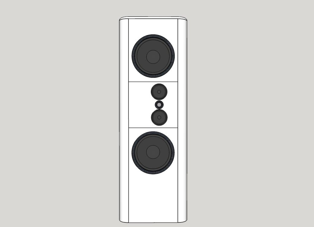
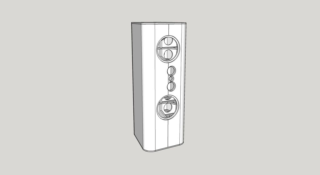
Made the tweeter a ScanSpeak D3004/6040-10, shifted everything up and squished it all together as much as I could while still allowing room for internal bracing and an internal enclosure for the mids. Center of the tweeter is now at 34.5".
-Chris
-Chris
Last edited:
Nifty.
Guessing each side will be a mirror image of the other.
Yep. Assuming the first one doesn't suck and I decide to actually build a second one.
-Chris
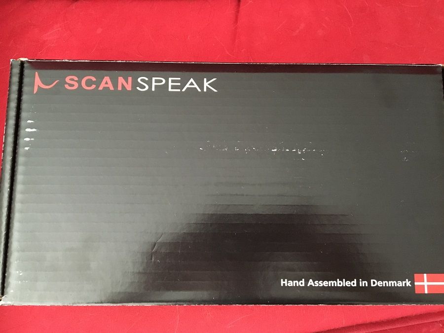
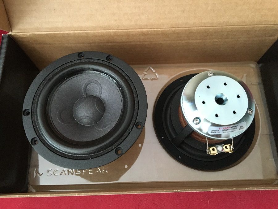
Little bit of goodness from Denmark arrived today. Man I can't wait to hear these things. If I had some tweeters I'd build a couple quick enclosures so I could listen to them while I build my big WMTMW monsters.
I've had an audio erection for these drivers since I saw measurements done a couple years ago.
-Chris
I've had an audio erection for these drivers since I saw measurements done a couple years ago.
-Chris
I've had an audio erection for these drivers since I saw measurements done a couple years ago.
-Chris
[
To much information!
😀
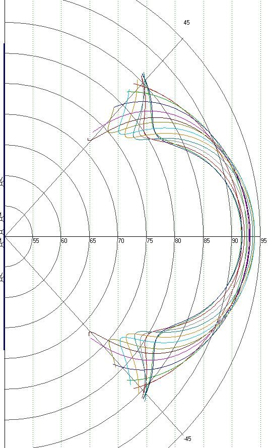
Finally got polar plots from SoundEasy. I had to go in and manually enter frequency response data based on published graphs since I don't have measured data in an enclosure yet. Since AE doesn't publish FR data I had to just make it up for the woofers but it should be close enough for this.
I didn't spend much time getting the FR perfect for the mids and tweeter either so it looks a little more ragged in my graphs right now than in the published data.
Spent a little time after that creating a passive crossover network that acoustically sums close enough to flat for what I'm doing right now. I'm doing everything digital but I'm pretty impressed with what SoundEasy came up with after just a couple hours of learning to use the built in passive filters and optimizer.
Here's the system response I was working with while creating my polar plots.
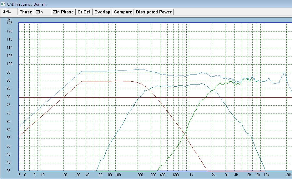
The horizontal plot is pretty boring at all frequencies, as expected with everything pretty much lined up vertically on the baffle. The vertical plot looks nice from 20Hz all the way through and well above my 250Hz crossover point between woofers and mids. Once you get up to about 900Hz you start to see the problems start and continue up until the two mids aren't contributing much any more.
Here's the vertical polar plot from 900Hz to 2200Hz, in steps of 100Hz.
I didn't spend much time getting the FR perfect for the mids and tweeter either so it looks a little more ragged in my graphs right now than in the published data.
Spent a little time after that creating a passive crossover network that acoustically sums close enough to flat for what I'm doing right now. I'm doing everything digital but I'm pretty impressed with what SoundEasy came up with after just a couple hours of learning to use the built in passive filters and optimizer.
Here's the system response I was working with while creating my polar plots.
The horizontal plot is pretty boring at all frequencies, as expected with everything pretty much lined up vertically on the baffle. The vertical plot looks nice from 20Hz all the way through and well above my 250Hz crossover point between woofers and mids. Once you get up to about 900Hz you start to see the problems start and continue up until the two mids aren't contributing much any more.
Here's the vertical polar plot from 900Hz to 2200Hz, in steps of 100Hz.
Last edited:
I tried moving the tweeter to the side so I could squeeze the mids 4cm closer together. Made a significant improvement vertically as you can see below.

Unfortunately I started seeing off axis horizontal issues through the crossover frequency range, on only one side. Didn't grab a screen print of that but I didn't like it.
So I think I'm going to stick with the mids and tweeter vertically lined up and live with the vertical off axis issues that go with it. Looking at the angles and shape of my ceiling, I think most of it is going to end up behind me anyway. And my floor is carpet so I'm not too worried about the response in that direction, through this frequency range.
The vertical sweet spot seems plenty tall enough to keep the response from changing with the recliners up or back.
-Chris
Last edited:
Great bunch of work you have presented.
And what a learning experience you must have gone through to produce this set of graphs.
I'll let you in on a little known secret in audio. There are no flat response curves in real listening positions.
It's a marketing fed illusion.
What you will find when you start to mesure is that our ears are remarkabl einstruments that will accomodate minor peaks and dips in certain frequency renages, and really hear those peaks, in the midrange. The dips are a little bit more dificult o hear if they are naroow.
So these are all simulations done with your measurements?
Thanks, Mark. I owe a truck load of thanks to you guys at DIYA, and especially Remi (krivium), for helping me learn enough to even know I should care about stuff like polar plots and off axis response.
I still haven't ordered tweeters and I'm still waiting for AE to finish building the woofers I ordered a couple weeks ago, so I haven't built any kind of enclosures to start getting measurements.
The drivers are all setup in SoundEasy with the real TS parameters and correct diameter/area for each one. But the frequency response data is from the graphs online at Madisound and is then blended with the sealed enclosure models at the internal volumes I plan to use. I left the acoustic center offsets at zero for this, with the assumption that I can use delay to make it look that way digitally.
I think that should make my polar plots accurate enough for now.
So, once I have the drivers installed in the actual speaker, I'll follow the SoundEasy guide from John K. to do near field measurements at low frequencies and time gated measurements above 225Hz or so. Then I'll go through most of the process again with real data measured in my box.
-Chris
The guide in SoundEasy is good. If you have any questions I'd be happy to help you out.
Note that you can do outside measurements if you have either a balcony or a large step ladder that are anechoic or free field to a pretty low frequency. And then you can splice in ground plane 2 meter low frequency measurements that are essentially the same.
You can run into some interesting things when trying to splice near filed and one meter measurements. They look all nice and wonderful. But when you get an opportunity to do a wide bandwidth true free filed measurement you see what is missing in the details.
Unfortunately it's noisy outside where I live so my only real choice is in the room where the speakers will live. I can get about 5 feet clear in all directions so that should get me a little lower than the 250Hz in the design guide.
Since the Dayton USB microphone I've had for a few years doesn't play nice with SoundEasy I bought an external sound card with mic pre-amp and a Dayton EMM-6 mic. So I guess I could haul everything down to my mom's house one weekend and get some measurements at the lower frequencies.
I'll see how the near field and splicing works out first though.
-Chris
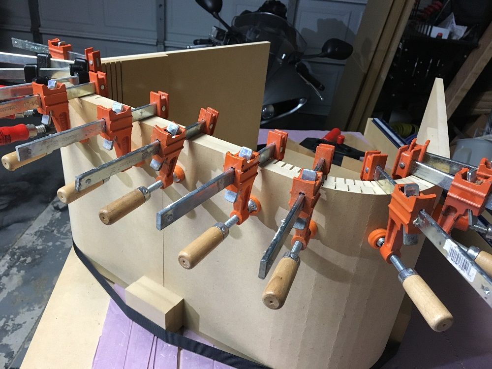
Did some test kerf cutting with the track saw since I'm off work today. Once I got the depth dialed in it worked really well and went reasonably fast. So I'm probably going to do my curved corners like this instead of ordering MDF sections. I'll reinforce inside with some fiberglass.
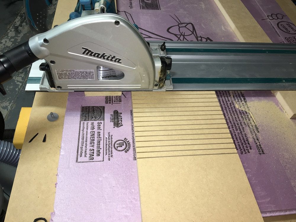
I'll tell you a little cabinet making trick. If you kerf cut two 1/2' layers and apply glue to them in the desired bent shape they will retain their shape. You can do this with kerfs to the interior and you will have a very strong joint. I usually roll on a very generous payer of wood glue on each side and then bend away.
Saves a bunch of fiber glass work.
Nice track saw. I use Makita cordless hand tools to. Great quality and reasonable prices. You might want to check out their cordless air nailer. That will be the next item I'm looking for. Get rid of my Rigid piece of crap.
Saves a bunch of fiber glass work.
Nice track saw. I use Makita cordless hand tools to. Great quality and reasonable prices. You might want to check out their cordless air nailer. That will be the next item I'm looking for. Get rid of my Rigid piece of crap.
I'll tell you a little cabinet making trick. If you kerf cut two 1/2' layers and apply glue to them in the desired bent shape they will retain their shape. You can do this with kerfs to the interior and you will have a very strong joint. I usually roll on a very generous payer of wood glue on each side and then bend away.
Saves a bunch of fiber glass work.
Nice track saw. I use Makita cordless hand tools to. Great quality and reasonable prices. You might want to check out their cordless air nailer. That will be the next item I'm looking for. Get rid of my Rigid piece of crap.
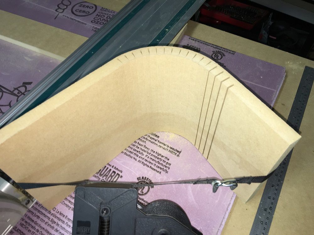
I like your suggestion on using two 1/2" layers with kerf cuts. After messing around with it some I redid my Sketchup model to have bent panels rather than pre made MDF radiused corners.
I cut some test pieces over the weekend so I could see how many kerf cuts I need for the inner and outer panels, and how tight of a curve would be doable. Ended up increasing my corner radius to 4.5" and settled on 3/8" spacing for inner panel kerf cuts and 1/2" spacing for the outer panel.
While I was at it I decided to taper in the sides toward the back. So my max width at the front will be 23" and it will taper down to 16" at the back.
I think I'm going to break up the panels into a few pieces to make it easier to work with them.
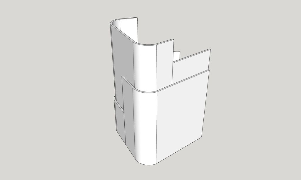
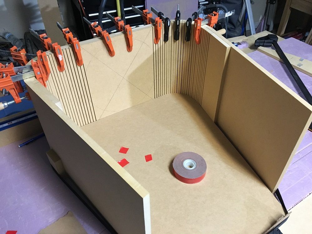
Also made a template I can use as a router pattern. Mocked up a crude section of the enclosure so I can work out my clamping strategy during glue up.
-Chris
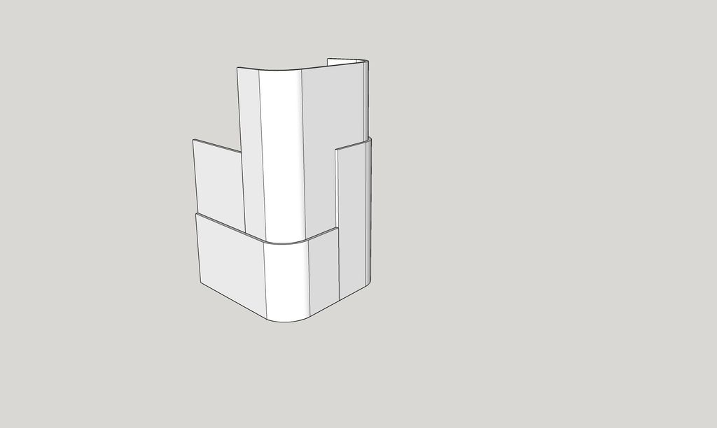
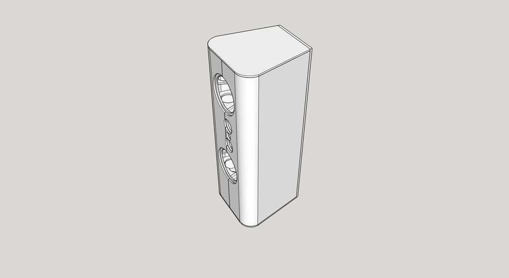
I think this should be the final model of what I'm going to build. At least externally. If it turns out as I hope, sound wise, I may veneer the sides to make it look nicer.
Last edited:
I have it modeled in Sketchup right now so that the woofers share the same air space. I don't think that would be any problem for the end speakers but it might make measuring difficult. So I might still figure out where to divide the enclosure so that both woofer have there own, equal air space.
-Chris
-Chris
More tips.
Fill the kerfs with PL premium.
It will give you a nice strong radius.
And you can put the kerf cuts face to face and have a smooth surface inside and outside should that matter to you.
That is going to weigh a ton!
Hope you are up lugging that monster around.
If it makes you think a bit, I'll tell you my thirty year audio cabinetry odyssey has ended up with thin and light. Bent panels that are pre-stressed and a goodly amount of internal bracing.
I'm done with 28mm MDF monkey coffins.
I made cabinets in the 80's out 28mm MDF one sheet weighed 189 pounds. I could lift it, put it on the table saw but heck if I could push it across!
Latest cabinet design work is here:
https://www.youtube.com/channel/UCjhL86Eih-SnTPGByh9RfKw
It might give you a few ideas.
You do some really nice work, Mark.
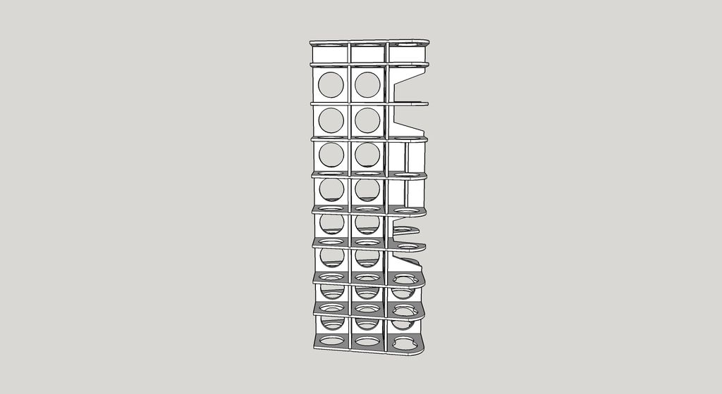
You're right about heavy. Using all MDF, I estimate 300 pounds without drivers, before cutting all the holes in the internal braces. Using plywood inside rather than MDF will knock a chunk off of that.
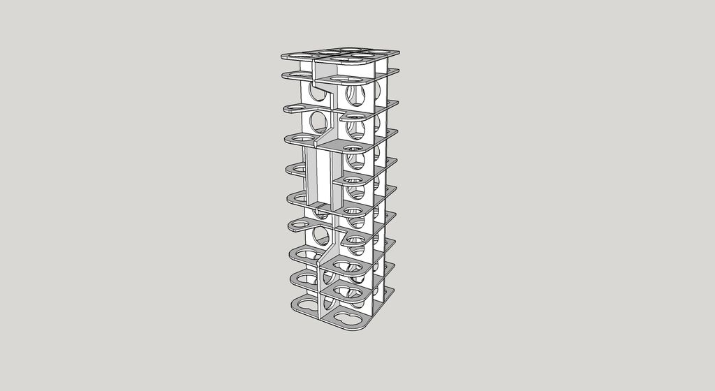
I've been thinking about only using a single vertical brace out toward each side wall rather than the two as I have it drawn now. It wouldn't save much weight but would save a fair amount of work since those 36 pieces have to be cut individually.
I also plan to be more aggressive with the bracing holes than shown in the drawing. And I'm probably going to make the rear panel removable.
Hopefully I can get the enclosure weight down closer to 200 pounds. I only have to move them from the garage to the room upstairs. Will be a pain to move around the garage after gluing the outer panels to the skeleton though.
-Chris
You're right about heavy. Using all MDF, I estimate 300 pounds without drivers, before cutting all the holes in the internal braces. Using plywood inside rather than MDF will knock a chunk off of that.
I've been thinking about only using a single vertical brace out toward each side wall rather than the two as I have it drawn now. It wouldn't save much weight but would save a fair amount of work since those 36 pieces have to be cut individually.
I also plan to be more aggressive with the bracing holes than shown in the drawing. And I'm probably going to make the rear panel removable.
Hopefully I can get the enclosure weight down closer to 200 pounds. I only have to move them from the garage to the room upstairs. Will be a pain to move around the garage after gluing the outer panels to the skeleton though.
-Chris
If you can get it consider using, 1/4 inch or 6mm MDF. It will hold it's shape if bent and glued in the manner you are considering. You can use your holy braces as glue up forms and use either an air nailer or temporary piloted screws to make your bent panels. (there are cordless air nailers available that are quite inexpensive. Or if you already have even a tiny compressor a pneumatic nailer can be bought at Harbor Freight for very little cost. Best investment you will ever get. Buy a nailer and a small bottle of air tool oil. I have similar nailers that are 20 years old. I give them 3 small drops of oil every couple of sticks of nails. And they purr along with no problems at all.
It will be surprisingly stiff and much lighter than what you have currently pictured.
The 6mm MDF is a much higher density than the normal stuff.
You have a nice box design I failed to type that. But I sure was thinking that!
Thanks for the compliment. I appreciate it. Considering how long I have been in this type of work that is the very least type of quality that should be expected. I always consider myself to be learning. And applying what I have learned. And I strive to do better on each project that I under take.
Over the weekend I ended up redrawing a lot of the internal bracing as 3/8" rather than 1/2". Since I plan on using a grid of dado cuts to align everything I can't really go thinner than that.
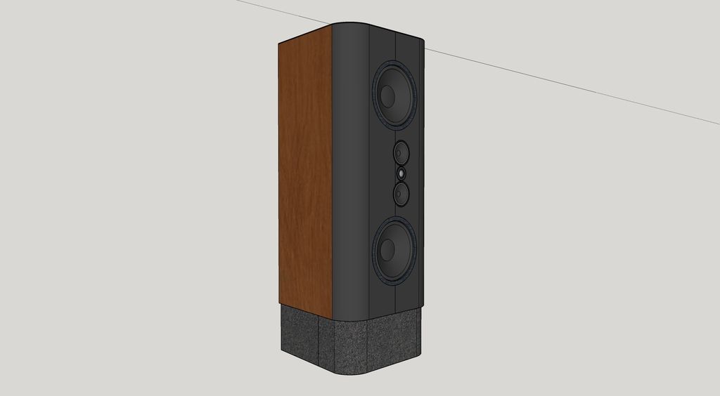
Since I have so much internal volume I decided to split the enclosure in half so that each woofer has its own air space. That meant blocking of a portion of the bottom, which then turned into building a shorter speaker with a separate stand. The stand will also serve as a cabinet for my amplifier modules.
So the only thing left to work out is how to build in some support for the huge magnets on these woofers and couple them to the enclosure skeleton. Shouldn't be too hard.
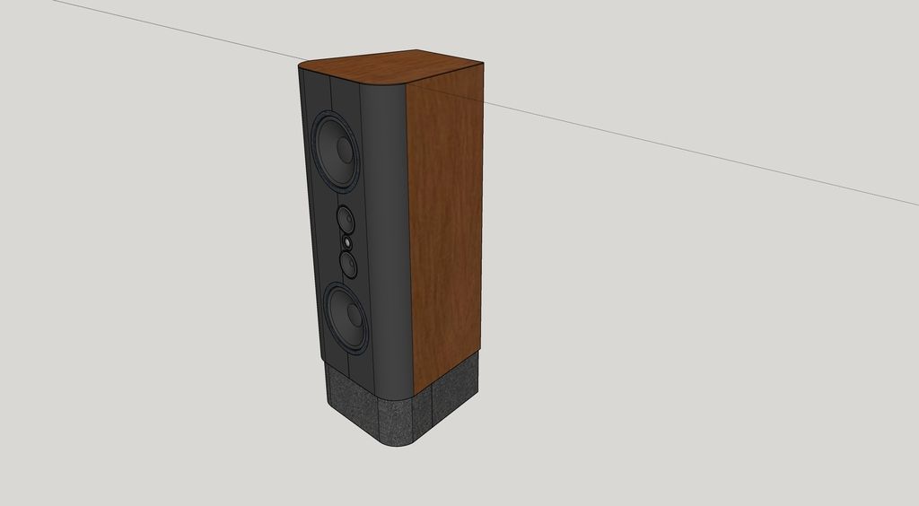
Haven't decided quite what the shape of the stand will be but below is what my speaker might look like with some simple veneer on the flat surfaces. I've never applied veneer and don't have access to a vacuum bag setup so I need to keep it simple. I think it looks pretty decent though.
-Chris
Since I have so much internal volume I decided to split the enclosure in half so that each woofer has its own air space. That meant blocking of a portion of the bottom, which then turned into building a shorter speaker with a separate stand. The stand will also serve as a cabinet for my amplifier modules.
So the only thing left to work out is how to build in some support for the huge magnets on these woofers and couple them to the enclosure skeleton. Shouldn't be too hard.
Haven't decided quite what the shape of the stand will be but below is what my speaker might look like with some simple veneer on the flat surfaces. I've never applied veneer and don't have access to a vacuum bag setup so I need to keep it simple. I think it looks pretty decent though.
-Chris
- Status
- Not open for further replies.
- Home
- Loudspeakers
- Multi-Way
- My attempt at 4-way digital active