Hi everyone,
Heres the parts I have so far
Exclusiv Online lens kit
- fresnels 160/305 (200x200x4mm)
- condenser 90x15mm
- reflector 55x20mm
- varifocal 265-330mm
(£59.07)
Izzotek 250W light kit
-all the bits
+front surface mirror 125x165x4
+FCC extension
(£79)
Ebay
-8" Hami 171x130 (stripped)
(£100)
Ebuyer
-4x 92mm fans
-4x92mm fan grills
Maplpin
-12v power supply
Misc
-PSU (for light box?)
Needed
-Wood (going to look in the shed)
-Nuts and bolts, louvered vents (trip to Wicks)
Total so far - £250ish (expected total - not much more than that)
The Plan
I have a rough plan but I need confirmation/help with a few things before I start building
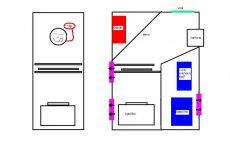
Basically I'm planning an upright design with a single mirror placed after the LCD/Fresnels
I believe it should be similar to this kind of design but with the LCD turned through 90 degrees for the upright design.
http://216.239.37.104/translate_c?hl=en&ie=UTF-8&oe=UTF-8&langpair=fr%7Cen&u=http://www.allinbox.com/bakobox/bakobox.htm&prev=/language_tools]allinbox[/URL]
Exclusiv online gives the following measurements for the lens kit
Reflector>HQI 1mm
>condenser 23.85mm
>Fresnel 136.15mm
>objective 285-330mm
Does the fresnel>objctive measurement refer to the surface of the second fresnel to the surface of the objective or its center?
I'm hoping to cover the finished projector so it looks like this
allinbox
On to the problems
1.Wiring!!!
I dont know a great deal about wiring and havent soldered anything since GCSEs design and tech. Having read some threads I dont particularly want to kill my self so...
This is how I see it
wall socket >Hami
>12v adaptor >4xFans
>Light Kit
The safest way i see of doing that is getting a 3way extension lead asnd sticking it in the box. Not really a compact solution.. How does everyone else wire it?
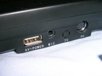
The Hami itself is confusing because it uses a single USB style port for power and video/audio inputs. It also has headphone out and a s-video style VGA input:
It seems most people do some kind of funky wiring in the box to allow placement of VGA/video/power inputs on the back of the projector. Is this simple to do?
I was thinking i'd just stick the whole hami panel on the back for simplicity.
2.Cooling
Do the MH lamp and FC2 holders actually need cooling or is it just the condenser and LCD/fresnels?
Also is the purpose of the metal boxed light boxes i've seen primaryly(spelling?) to reduce escaped light or to protect against exploding light bulbs - I mean i've seen some light sources that do without the metal box and just use the reflector/condenser.
Is the fan placement i've suggested below ok?
Heres the parts I have so far
Exclusiv Online lens kit
- fresnels 160/305 (200x200x4mm)
- condenser 90x15mm
- reflector 55x20mm
- varifocal 265-330mm
(£59.07)
Izzotek 250W light kit
-all the bits
+front surface mirror 125x165x4
+FCC extension
(£79)
Ebay
-8" Hami 171x130 (stripped)
(£100)
Ebuyer
-4x 92mm fans
-4x92mm fan grills
Maplpin
-12v power supply
Misc
-PSU (for light box?)
Needed
-Wood (going to look in the shed)
-Nuts and bolts, louvered vents (trip to Wicks)
Total so far - £250ish (expected total - not much more than that)
The Plan
I have a rough plan but I need confirmation/help with a few things before I start building
Basically I'm planning an upright design with a single mirror placed after the LCD/Fresnels
I believe it should be similar to this kind of design but with the LCD turned through 90 degrees for the upright design.
http://216.239.37.104/translate_c?hl=en&ie=UTF-8&oe=UTF-8&langpair=fr%7Cen&u=http://www.allinbox.com/bakobox/bakobox.htm&prev=/language_tools]allinbox[/URL]
Exclusiv online gives the following measurements for the lens kit
Reflector>HQI 1mm
>condenser 23.85mm
>Fresnel 136.15mm
>objective 285-330mm
Does the fresnel>objctive measurement refer to the surface of the second fresnel to the surface of the objective or its center?
I'm hoping to cover the finished projector so it looks like this
allinbox
On to the problems
1.Wiring!!!
I dont know a great deal about wiring and havent soldered anything since GCSEs design and tech. Having read some threads I dont particularly want to kill my self so...
This is how I see it
wall socket >Hami
>12v adaptor >4xFans
>Light Kit
The safest way i see of doing that is getting a 3way extension lead asnd sticking it in the box. Not really a compact solution.. How does everyone else wire it?
The Hami itself is confusing because it uses a single USB style port for power and video/audio inputs. It also has headphone out and a s-video style VGA input:
It seems most people do some kind of funky wiring in the box to allow placement of VGA/video/power inputs on the back of the projector. Is this simple to do?
I was thinking i'd just stick the whole hami panel on the back for simplicity.
2.Cooling
Do the MH lamp and FC2 holders actually need cooling or is it just the condenser and LCD/fresnels?
Also is the purpose of the metal boxed light boxes i've seen primaryly(spelling?) to reduce escaped light or to protect against exploding light bulbs - I mean i've seen some light sources that do without the metal box and just use the reflector/condenser.
Is the fan placement i've suggested below ok?
Attachments
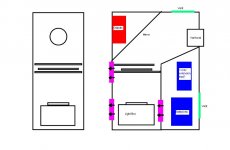

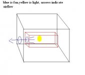
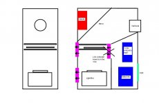
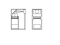
Regarding your fan placement, most people use a setup that allows the air in the light box (or light area) to be sucked out of the entire casing. You don't want to have air being blown on the bulb and sucked out at the same time as this shortens bulb life. I made a generic sketch, hopefully it helps
Attachments
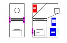
Yeah, I agree with the vent at the top possibly being a problem.
Still not sure about the cooling though (see my queries above). Additionally if there's just the one fan sucking air out of the light box isn't air still being sucked over the bulb causing the same problems?
How concentrating the fans on the lcd/fresnel(acrylic) unit... problem in my design one of the LCDs boards is going to be in the way
Attachments
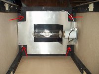
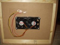
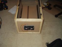
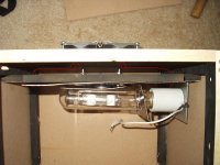
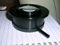
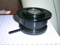
Yea air would be flowing over the bulb I guess, but not forced cooler air. Not sure if that makes such a difference. I'm doing a 15.4" projector and incorporated Inkog's idea. I have yet to try it as im still in the building stage. Here's some pics. That is an 18" ruler laying inside. The inside dimensions are 14"W by 11"H 
Oh yea, the red arrows depict the airflow to the fans. There's roughly 3/4" between the back of the light and the fans.
Oh yea, the red arrows depict the airflow to the fans. There's roughly 3/4" between the back of the light and the fans.
Attachments
The backside (2x80mm fans). These fans are incredible. 3000rpm at 25-26dba!!! got them from www.nexfan.com. The actual fan http://store.yahoo.com/nexfan03/evcafan80bl.html
Attachments
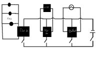
Ok, so heres my less than GCSE physics interpretation of how everything should be wired.
1. Where does the earth wire come into it?
2. Can i just use the 12v Hami(LCD) power source for the fans too?
3. When it comes to connecting the 12v adaptors can i just somehow get rid of the 3 pins on the casing and attach the 240v wires internally
4. How should I fuse the whole thing?
As you can see i really dont have a clue. Any help's appreciated
Attachments
I wouldn't recommend wiring the fans to the Hami's power board only because you don't want to overload it and fry the chip (then you'd be sol  ). For my four fans, I bought a 120v to 12v converter (cause im in the USA) at 1500ma and this bad boy can power nearly 6x80mm fans at full speed. Try to look for one, they cost areound 20 dollars here and I don't think there's a radioshack in Europe, but who knows. You want at least 1500ma, I don't remember off hand how much a fan gernerally uses but just know that 1500 should be enough for your cooling needs. For 4) you can simply put an inline fuse into any positive line. Fuse off the ballast's positive input, the Hami's input and the 12v powersupply. 3) im not really sure what you mean. Do you mean remove the plug and solder the input directly to the board? If so go for it, just make sure you don't "splash" the solder 🙄
). For my four fans, I bought a 120v to 12v converter (cause im in the USA) at 1500ma and this bad boy can power nearly 6x80mm fans at full speed. Try to look for one, they cost areound 20 dollars here and I don't think there's a radioshack in Europe, but who knows. You want at least 1500ma, I don't remember off hand how much a fan gernerally uses but just know that 1500 should be enough for your cooling needs. For 4) you can simply put an inline fuse into any positive line. Fuse off the ballast's positive input, the Hami's input and the 12v powersupply. 3) im not really sure what you mean. Do you mean remove the plug and solder the input directly to the board? If so go for it, just make sure you don't "splash" the solder 🙄so no connecting the fans to the Hami then.
I've got a 240v to 12v converter but its only 500ma..hopefully for 3 fans it should be ok. In any case at least they'll be quieter.
Any idea what kind of fuses to use?
"Do you mean remove the plug and solder the input directly to the board" yup, thats what i mean. Think i'll ask someone with soldering experience to help me out actually doing it
thanks for the replies so far, gonna start building the box tomorrow
You're welcome. You should look on your ballast, it should tell you the amperage. I have a 400w electronic ballast and it is 3.33amps (120v). Im not sure if amperage changes with the change in voltage but it should be listed on your ballast. Well, im gonna compare this to the audio setup in my car. I'm running a total of 1180watts in my car with an 80amp fuse which is about 14.75 amp fuse for every 80 amps. If you get the amp to fuse ratio is (0.184375). Multiply that by the amps on your ballast and I would need like a (0.184375x3.33) .5-1amp fuse. You should have someone check on this because Im no eletrician but i think its adequate enough. I did this analogy because both are 12v supplies.
Hi again,
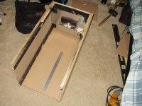
tried bulding a mock up out of cardboard box just to get an idea of how everything will fit together. unfortunatly i'm still having problems with the dimensions..
I've got a fl=305 second fresnel and a varifocal 265-330mm.
1.Should it be a case of, as in the attached image, the surface of the projection lens being 305mm away from the fresnel of does it have to be closer so the light covers the whole aperture.
2.Should the varifocal be set to the 265 or 330mm setting when taking point 1 into account.
Attachments
- Status
- Not open for further replies.
- Home
- General Interest
- Everything Else
- The Moving Image
- DIY Projectors
- My 8" projector