juergenk said:but the hum-voltage after the rectifier would be less with a 3phasic-bridge?
3 pulses at 50 hz=150 pulses
or
3 pulses at 60 hz=180 pulses
or double for full wave bridging.
1 pulse for single phase 1/2 wave or 2 pulses for full wave rectification= 60 or 120 hz.
Not counting induced currents.
more pulses, but less intense I guess
because the one big charge pulse at the capacitor is divided up into three smaller ones 😕
I have build 3-phasic heating supplies, but no experience with 3-phasic rectification.
So I am curious. 🙂
because the one big charge pulse at the capacitor is divided up into three smaller ones 😕
I have build 3-phasic heating supplies, but no experience with 3-phasic rectification.
So I am curious. 🙂
juergenk said:more pulses, but less intense I guess
because the one big charge pulse at the capacitor is divided up into three smaller ones 😕
I have build 3-phasic heating supplies, but no experience with 3-phasic rectification.
So I am eager to learn. 🙂
'hum' is repetative pulses.
The cap recharges on every pulse
Som Mark Levinson amps convert the incoming mains to 3-phase 440 V to make it easier to smooth out the ripple. Since it is aircraft standard, they can also make use of certain technologies from that field. I don't think they say how they make the conversion and if it is really worth the price compared to using the same amount of $$$ on big caps an chokes instead.
Glen,
clever with the floating supplies. I assume they are just separate windings on the transformer with ordinary rectification and caps. However, the crossover artifacts from the class AB stage will bleed through to the supply of the class A stage, I suppose? Of course, that is much better than having them directly at the output.
Hartono said:If you build it, probably you will be on world's class A hall of fame. 1000 watt class A
Sorry, I just strapped 5 XA200.5's in parallel and got that.
😎
Nelson Pass said:
Sorry, I just strapped 5 XA200.5's in parallel and got that.
😎
Isn't it summer in California? Sounds more like a winter experient, I think. 🙂
With all the variations on amp design is there really a benifit of having a 1000w amplifier rather than the 20-30w or even 3w designs out there?
What sort of speakers are you driving/how big is your listening room?
I have some fairly effecient speakers and have given them 100 class A watts, 5/6 class A watts and 10 digital watts. My favourites are the smaller amps, especially the little class A one. I get the control of class A over AB for example but cant see the benefit of 1000w in any residential setting.
Just so you know these are genuine questions and not meant to start an argument 🙂
G.Kleinschmidt said:
All up it will be a lot more than that. I've ordered four 200VA EI (split bobbin - better primary-secondary isolation than a toroid) transformers to provide the floating supplies for the class-A stages. These weigh 2.8kg each.
A pair of 2kV toroidal transformers supply the class B stages. I don’t know what these will weigh.
There are also various little transformers for ancillary stuff.
Incidentally, whilst finalising the transformer order and looking into available electrolytic capacitors, I have revised the amplifiers rated power/load impedance again 🙄
The amplifier is now going to be built to deliver 1000W rms per channel (continuous sinewave) into 2 ohms, not 4 ohms. This is much more sensible, as a pair of 4 ohms speakers (or even a quad of 8 ohm speakers) can be paralleled to make a 2 ohm load. Ever seen a 4 ohm 1kW speaker in a HiFi shop 🙂 ) ??
The 2 ohm rating also means that the class-B supply voltages can be kept well below +/-100V (1kW rms into 2ohms = 63.2V peak). Electrolytic filter capacitors for supply voltages below 100V are much cheaper and easier to obtain.
Phew. I’ll get back to the (final?😕 ) version schematics and PCB layouts now.
Cheers,
Glen
Nice work I must say, I like crazy all out designs.
As I read this is it going to be a single amplifier chassis?
I very strongly suggest that you go to mono blocks, after having lived with a few amplifiers that were too difficult to move. You also get twice the line power.
Cutting those heat sinks in half would make a lot of sense.
On the other hand that huge tower would certainly make a visual statement. You'll certainly have the tallest audio amplifier ever made!
Pete B.
Myhrrhleine said:Might want to consider mains circuit breaker derating too.
20A@120V should (barely) power 2 channels.
If it were me, I'd run a new 240V circuit, with a minimum 10ga. wires.
Such an amp deserves a good power supply.
[/B]
Well I’ve got a 50A@240V outlet in my shed for dummy load testing things such as this:
http://users.picknowl.com.au/~glenk/CTM2K.HTM
So testing the amplifier at it’s maximum power output shouldn’t be much of a hassle.
The complete stereo amplifier will only have an idle dissipation of about 650W in total. Most of this is provided by the quiescent dissipation of the class A stages, which remain constant, regardless of what the amplifier is doing. 650W is less than the “low” setting of a typical fan heater.
When amplifying music (instead of continuous sinewaves), even with the volume turned up to the onset of clipping, the average power delivered to the load will never come close to the peak power. A single power point will power it easily, and I do not envisage ever having to crank the volume up to anywhere near maximum in my loungeroom 🙂 . I will provide each channel with it’s own 240V AC inlet though, so that each channel can be plugged into a separate circuit.
Christer said:Glen,
clever with the floating supplies. I assume they are just separate windings on the transformer with ordinary rectification and caps. However, the crossover artifacts from the class AB stage will bleed through to the supply of the class A stage, I suppose? Of course, that is much better than having them directly at the output.
Yes they do but there are a few important points. The crossover distortion presented to the supply of the class a core is not that of the class B output stage alone, but that of the complete class B amplifier after being reduced by global negative feedback. The crossover artefacts on the class A rails are attenuated greatly at the class A output, and what little does make it through is reduced again by the global negative feedback of the complete class A amplifier (In my design, I have added Hawksford Error Correction to the class A stages as well).
This is discussed in length, along with a basic mathematical analysis, in the AES paper linked to earlier. There are also other benefits of the A+ scheme, such as the fact that Cob of the output transistors in the class A stage is effectively bootstrapped by the output-tracking supply rails. The linearity of the class A stage is actually improved. The paper lists other benefits and actually makes the claim that class A+ is not only better than class B, but better than conventional class A as well.
Oh, I don’t mind heavy 🙂. I thought about the monoblock idea, but nah, that just isn’t anywhere near as impressive.PB2 said:
Nice work I must say, I like crazy all out designs.
As I read this is it going to be a single amplifier chassis?
I very strongly suggest that you go to mono blocks, after having lived with a few amplifiers that were too difficult to move. You also get twice the line power.
Cutting those heat sinks in half would make a lot of sense.
On the other hand that huge tower would certainly make a visual statement. You'll certainly have the tallest audio amplifier ever made!
Pete B.
Cheers,
Glen
Re: Ouch
LOL!
Don't worry, I'm mostly building this thing for the fun of it. It will mostly be an extravigant showpiece in my loungeroom, with a much lower power amplifier being used for general duties. The only time this amplifier will be used for long periods is in cold weather, when the heat dissipated will just contribute to my house heating, so my net carbon footprint shouldn’t be increased by too much 🙂
Cheers,
Glen
JRKO said:What will this thing be pulling out of the wall?
Your carbon footprint will be soooooo big and deep kids will be able to use it as a skatepark😱
LOL!
Don't worry, I'm mostly building this thing for the fun of it. It will mostly be an extravigant showpiece in my loungeroom, with a much lower power amplifier being used for general duties. The only time this amplifier will be used for long periods is in cold weather, when the heat dissipated will just contribute to my house heating, so my net carbon footprint shouldn’t be increased by too much 🙂
Cheers,
Glen
1KW+ AMP
Have you considered using a PWM output stage for the main source of power and then using a much smaller, high accuracy, class A amplifier in an error correction mode?
Such a design would give you the high efficiency of class-D with the high accuracy, low distortion of class A.
It would also save a ton of copper, aluminum, and silicon. not to mention CO2.
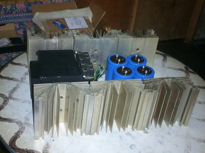
this is what i'am aiming at.....traffo has a core of 2.25 in stacked 5.5 inches and weighs in at 22kgs.....
 😀
😀
Re: 1KW+ AMP
Yes, I did consider it, but low dissipation and design compactness are not listed objectives on my project specification! The majority of the dissipation comes from the class A stage. The savings, dissipation wise, from going class D instead of class B are minimal.
The cost and weight savings could be significant, but my aim with this design is to produce a very high powered amplifier with very little distortion. The output of the class A stage is not entirely immune to what appears on the tracking supply rails. High frequency artifacts are particularly troublesome. It is very difficult to build a switching amplifier of such power rating whose output is as clean as that of a good class B amplifer.
Except for mosty the number of devices used in the output stages and the EC applied to the class A output stages, the class A and class B amplifiers in my design are idential.
Cheers,
Glen
analog_guy said:Have you considered using a PWM output stage for the main source of power and then using a much smaller, high accuracy, class A amplifier in an error correction mode?
Such a design would give you the high efficiency of class-D with the high accuracy, low distortion of class A.
It would also save a ton of copper, aluminum, and silicon. not to mention CO2.
Yes, I did consider it, but low dissipation and design compactness are not listed objectives on my project specification! The majority of the dissipation comes from the class A stage. The savings, dissipation wise, from going class D instead of class B are minimal.
The cost and weight savings could be significant, but my aim with this design is to produce a very high powered amplifier with very little distortion. The output of the class A stage is not entirely immune to what appears on the tracking supply rails. High frequency artifacts are particularly troublesome. It is very difficult to build a switching amplifier of such power rating whose output is as clean as that of a good class B amplifer.
Except for mosty the number of devices used in the output stages and the EC applied to the class A output stages, the class A and class B amplifiers in my design are idential.
Cheers,
Glen
OK...............
For anyone interested, I've just finished the schematic for a major part of the amplifier, and have started the web page documentation. Here it is:
http://users.picknowl.com.au/~glenk/MAIN.HTM
Now onto the regulated +/-80V power supply board........
Cheers,
Glen
For anyone interested, I've just finished the schematic for a major part of the amplifier, and have started the web page documentation. Here it is:
http://users.picknowl.com.au/~glenk/MAIN.HTM
Now onto the regulated +/-80V power supply board........
Cheers,
Glen
I never listened to this kind of amp, but was considering it also, before I became a class D victim.
From my perspective this concept is promising. The distorsion of the class B part will be seen only in the rails of the class A output stage and will affect the class A output only in massively reduced way, depending on the Ic vs Uce characteristic of the class A output devices.
If we consider to use some small idle in the class B stage and make it AB, then this concept should be able to show highest performance. From theory I like it.
...curious for your results...
ChocoHolic said:I never listened to this kind of amp, but was considering it also, before I became a class D victim.
From my perspective this concept is promising. The distorsion of the class B part will be seen only in the rails of the class A output stage and will affect the class A output only in massively reduced way, depending on the Ic vs Uce characteristic of the class A output devices.
Actually, it is feedback via the collector-base capacitance (Cob) of the output devices which is the greatest contributor. BJT transconductance is very high and practically insignificant in comparison.
The feedback via Cob can be reduced to very low levels throughout the audio band by presenting a low drive impedance to the output devices though.
Cheers,
Glen
G.Kleinschmidt said:
Actually, it is feedback via the collector-base capacitance (Cob) of the output devices which is the greatest contributor.
Most probably, which is also why HF components of the crossover distorsion might sneek in. I am not saying this will be problem in practice, but obviously the PSRR of the output stage matters a lot if we want to avoid the EC having to do as much job as it would in a class B stage. You could go one step further and cascode the output transistors, referenced to the amp output. Yes, it might be overdoing it, but what's the difference between overdoing and overdoing a little bit more? 🙂
Another thing that I think has not been mentioned and which differs from ordinary class A is the average power and temperature. While Icq is constant, just as in class A, Vceq is not. Hence the average power and thus the average temperature will vary, changing the operating conditions in a way that won't happen in ordinary class A.
Oh well, enough of theoretical knitpicking. It is a very interesting and clever design Glen, and I think we are all looking forward to learn about how it will eventually perform in practice.
Christer said:
Another thing that I think has not been mentioned and which differs from ordinary class A is the average power and temperature. While Icq is constant, just as in class A, Vceq is not. Hence the average power and thus the average temperature will vary, changing the operating conditions in a way that won't happen in ordinary class A.
Too late to edit previous post, but forget this part of what I wrote. I don't know what I was thinking about. Mixed your approach up with tracking rails, probably.
- Status
- Not open for further replies.
- Home
- Amplifiers
- Solid State
- My 1024W RMS CLASS A+ amplifier.