Hi, I'm using this board:
https://nl.aliexpress.com/item/4000..._main.391.21ef79d2PIMP8L&gatewayAdapt=glo2nld
Powered by an ILP 7UR30, 30-0-30V 5A toroid transformer switched on via a softstart module.
The on/off switch is one with built in lighting, which switches a 12V transformer, which in turn powers a relay which switches the 230V to the soft start, as I wasn't comfortable switching the mains via the relative small on/off switch. Mayby overly complex, but it works.

The amp works very well, impressive bass and minimal heat on the chip (35°C after a night of running), the picture above shows the first test set-up using a low-pass filterboard, powering a subwoofer.
What's annoying is the 'thump' when switching the power off, even after I added a relay board, which works fine when powering up, switching on the speaker output with a delay, but it's obviously too slow to prevent the thump switch off noise.

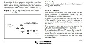
I read in the datasheet that there is a built in standby/mute circuit in the TDA7294:
"Other features
The device is provided with both stand-by and mute functions, independently driven by two CMOS logic
compatible input pins.
The circuits dedicated to the switching on and off of the amplifier have been carefully optimized to avoid any kind
of uncontrolled audible transient at the output.
The sequence that we recommend during the ON/OFF transients is shown by Figure 18.
The application of Figure 19 shows the possibility of using only one command for both st-by and mute functions.
On both the pins, the maximum applicable range corresponds to the operating supply voltage"
I should not need a relay board.
The pins required are not connected by the manufacturer of my board, but I can solder a thin wire directly onto the pin.
But am I correct in understanding that I need to connect the supply voltage (30V!)to that in in order to activate the mute function?
That's scary...
Is there a schematic showing how to wire the mute/standby function, completely, so even a 70 year old (me) can understand it?
Regards, Jan.
https://nl.aliexpress.com/item/4000..._main.391.21ef79d2PIMP8L&gatewayAdapt=glo2nld
Powered by an ILP 7UR30, 30-0-30V 5A toroid transformer switched on via a softstart module.
The on/off switch is one with built in lighting, which switches a 12V transformer, which in turn powers a relay which switches the 230V to the soft start, as I wasn't comfortable switching the mains via the relative small on/off switch. Mayby overly complex, but it works.
The amp works very well, impressive bass and minimal heat on the chip (35°C after a night of running), the picture above shows the first test set-up using a low-pass filterboard, powering a subwoofer.
What's annoying is the 'thump' when switching the power off, even after I added a relay board, which works fine when powering up, switching on the speaker output with a delay, but it's obviously too slow to prevent the thump switch off noise.
I read in the datasheet that there is a built in standby/mute circuit in the TDA7294:
"Other features
The device is provided with both stand-by and mute functions, independently driven by two CMOS logic
compatible input pins.
The circuits dedicated to the switching on and off of the amplifier have been carefully optimized to avoid any kind
of uncontrolled audible transient at the output.
The sequence that we recommend during the ON/OFF transients is shown by Figure 18.
The application of Figure 19 shows the possibility of using only one command for both st-by and mute functions.
On both the pins, the maximum applicable range corresponds to the operating supply voltage"
I should not need a relay board.
The pins required are not connected by the manufacturer of my board, but I can solder a thin wire directly onto the pin.
But am I correct in understanding that I need to connect the supply voltage (30V!)to that in in order to activate the mute function?
That's scary...
Is there a schematic showing how to wire the mute/standby function, completely, so even a 70 year old (me) can understand it?
Regards, Jan.
Last edited:
Dear Mr. Jan
I'm sorry if I have a mistake assuming the pictures that you provided, but I think in the first picture you assembled the amplifier without the speaker protector board and in the second picture, the amplifier (with the active filter board changed), you added the speaker protector board.
And if I traced the blue twisted cable of the AC supply for the speaker protector board, it is connected to the 12V transformer near the power switch and big toroid (different transformer from the toroid that supply the amplifier board)...
I always connect the speaker protector AC supply to the same transformer that I use to power up the TDA7294 board.
So when the main transformer that supply the amplifier board loosing power (switched Off), than the speaker protector will loosing the power quicker than the amplifier, releasing the relays off, hence the thump off power noise never heard on speakers...
Here in my place, the secondary transformer winding comes in many AC output taps, for example 30V-24V-18V-12V-CT-12V-18V-24V-30V.
If my Amplifier Board need 24VAC CT for the AC Input, then I use the 24V - CT -24V and I use the 12V - CT - 12V for the speaker protector board (the CT will have 2 branch cable, one to the GND of amplifier power supply board, and the other to the GND of the speaker protector board).
On the other hand, the mute and stand by features for the TDA7294 chip, since you have used the comercial board, I assume they have designed the supply for these features as the data sheet suggested.
Tweaking the tiny board and double sided board will lift the trace, and broke the board with the risk of the IC being explode because of the solder blob or disconnected trace that sometimes we didn't notice.
But maybe the other DIY Audio Enthusiast will spark new solutions for Mr. Jan.
Best regards
Salim
Hi Salim,
Thank you for your reply.
You are correct, the pictures show different set-ups; the first one without the speaker protection board generated a lot of noise when disconnected from the power supply, due to the capacitors of the low pass filter discharging while the amp was still playing for a few seconds on the remainder of the power supply of it's capacitors.
The second one shows the added speaker protection board and another filter board (used in another thread: https://www.diyaudio.com/community/threads/scratchy-pot-on-tenghong-low-pass-filter.401145/page-3 but not related to the muting issue).
Again I used the seperate power supply for the speaker protection, as that is what the data of these boards say is preferable.
I have to say, that on other builds, I have added extra secondairy windings to the main toroid, to power the low-pass filter used.
Using a secundairy winding for the speaker protection sometimes worked, but in most occasions it reacted too slow to beat the switching off noises...
Soldering a thin wire to the pins of the TDA9273 without lifting the pads is no problem, I've assembled many circuitboards.
It's finding a 'proper' schematic on how to activate the mute/standby options that is my prime concern.
Regards, Jan.
As I frequently misspell the chip I'm asking about: it's the TDA7294...

I can't figure out how to use the standby/mute function.
When I look at the pinout, using pin 9 and 10, what's VM and VSTBY and most importantly: where do I connect them to?

Further down the datasheet there's this layout, with a single mute/standby; again, where do I connect the white dot to?

I currently power up the amp with the mains switch (big thump powering down), how do I combine that with the mute/standby option?
Regards, Jan.
I can't figure out how to use the standby/mute function.
When I look at the pinout, using pin 9 and 10, what's VM and VSTBY and most importantly: where do I connect them to?
Further down the datasheet there's this layout, with a single mute/standby; again, where do I connect the white dot to?
I currently power up the amp with the mains switch (big thump powering down), how do I combine that with the mute/standby option?
Regards, Jan.
lifting the 22k resistor and add a "standby-on" switch or relay contacts and see if that gets rid of the thump.

Hi Chris,
I'll give it a go, but if it works, it adds another switch to operate to mute the amp. How do I incorporate that with the normal mains switch?
Regards, Jan.
I'll give it a go, but if it works, it adds another switch to operate to mute the amp. How do I incorporate that with the normal mains switch?
Regards, Jan.

Hi Savan,
I think I can realize that, but how do I incorporate that with the normal mains switch?
Regards, Jan.
I think I can realize that, but how do I incorporate that with the normal mains switch?
Regards, Jan.
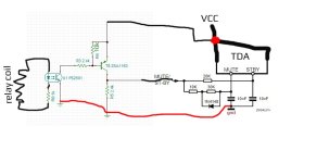
Don't use mains from relay, use for example an opto transistor to supply mute pin from VCC of the TDA, connect led of the opto transistor to relay coil. I using the similar technique to eliminate any bumps while swithing amplifier off, for example I have SMPS which have stdby input, so when I turn off amplifier trought relay I have added an opto transistor directly to coil of the relay pins as an open colector and trought opto transistor activating stdby of the SMPS, that way I have eliminated bumps.
follow the figure
follow the figure
Attachments
Last edited:
I had to look that up: https://nl.wikipedia.org/wiki/Optocoupler
This means extra circuitry with an extra powersupply?
Doesn't that mean I put 30V on the mute pin? Scary...
Regards, Jan.
This means extra circuitry with an extra powersupply?
Doesn't that mean I put 30V on the mute pin? Scary...
Regards, Jan.
No! See figure 17 from picture above! You just need to comply with figure 17. Stdby+mute in that case is active, it need to be connected to VCC of the supply of the TDA to unmute, ot if there is no VCC at those pin you have mute by default.! But you can add an opto npn transistor in combination with pnp transistor (non opto) to make an open colector with your coil on relay, and in the same time isolated input from your relay coil. So when you press power button and it activate relay the same time it will mute-unmute TDA, or wice versa.
but if it works, it adds another switch to operate to mute the amp. How do I incorporate that with the normal mains switch?
Use a double pole switch.The on/off switch is one with built in lighting, which switches a 12V transformer, which in turn powers a relay which switches the 230V to the soft start, as I wasn't comfortable switching the mains via the relative small on/off switch.
Something like this. When you press power button opto will be faster than relay coil so booth mute and stdby will be allready active before relay and you will eliminate any bumps. You should put smaler capacitors to figure 17 to get faster response of the mute & stdby
Attachments
Last edited:
Isn't this a more complex version of what Chris suggests?No! See figure 17 from picture above! You just need to comply with figure 17. Stdby+mute in that case is active, it need to be connected to VCC of the supply of the TDA to unmute, ot if there is no VCC at those pin you have mute by default.! But you can add an opto npn transistor in combination with pnp transistor (non opto) to make an open colector with your coil on relay, and in the same time isolated input from your relay coil. So when you press power button and it activate relay the same time it will mute-unmute TDA, or wice versa.
I'm currently using both relays of the speaker protection in parallel; I could change that and use one relay for the speaker lead and the other to switch the 22K on, or off as required.
If you don't mind, I'll try that before I start looking in my parts box to see if I have at hand what's required for the more elaborate version.
Regards, Jan.
Ok you are right, I just provided example how I have eliminated bump when I power off my aplifier, I just added opto transistor npn and another pnp and suplied opto from power on-off coil directly, my power on-off is digitaly controled relay and it was the easy way to do stdby function on my SMPS
This is similar in relation to
You should connect circuit above directly to relay coil and it will activate mute&stdby till before your relay coil get charged/discharged.
Edit: I don't know how many volts mute & stdby pin accepts on TDA but you need to research that and in case your VCC is high for those pins try add some resistor divider at the input of the mute and stdby!
This is similar in relation to
Powered by an ILP 7UR30, 30-0-30V 5A toroid transformer switched on via a softstart module.
The on/off switch is one with built in lighting, which switches a 12V transformer, which in turn powers a relay which switches the 230V
You should connect circuit above directly to relay coil and it will activate mute&stdby till before your relay coil get charged/discharged.
Edit: I don't know how many volts mute & stdby pin accepts on TDA but you need to research that and in case your VCC is high for those pins try add some resistor divider at the input of the mute and stdby!
Last edited:
Thank you gents!
I'll get working on it first thing tomorrow, as I'm being called in for dinner.
I'll let you know how things go.
Regards, Jan.
I'll get working on it first thing tomorrow, as I'm being called in for dinner.
I'll let you know how things go.
Regards, Jan.
Last edited:
I'm currently using both relays of the speaker protection in parallel; I could change that and use one relay for the speaker lead and the other to switch the 22K on, or off as required.
I thought the speaker relay was too slow to reacts during power off?
I think changing the power switch to a double pole switch would be a better option, the speaker relay will handle (if there) power on thump and the double pole switch will instantly mute the amp during power off.
Last edited:
Hi Chris,
I'll give both ways a try, if the speaker relay is indeed too slow, I'll go for the double pole switch.
Regards, Jan.
I'll give both ways a try, if the speaker relay is indeed too slow, I'll go for the double pole switch.
Regards, Jan.
Hi Jan,
Another option is use a 12V relay connect to the power switch, or use your existing relay if it has extra pair of contacts.
I think the speaker relay was too slow to reacts during power off, that's why you need to look for other solutions.
Another option is use a 12V relay connect to the power switch, or use your existing relay if it has extra pair of contacts.
I think the speaker relay was too slow to reacts during power off, that's why you need to look for other solutions.
Hi Chris,
The relay that switches the the soft start for the toroid only has a single pair of contacts (NO or NC), but I could use a second relay for the mute function. Advantagious is the fact this relay reacts very quick as the powersource is slightly anemic (17 V for a 24V coil)...
Regards, Jan.
The relay that switches the the soft start for the toroid only has a single pair of contacts (NO or NC), but I could use a second relay for the mute function. Advantagious is the fact this relay reacts very quick as the powersource is slightly anemic (17 V for a 24V coil)...
Regards, Jan.

- Home
- Amplifiers
- Chip Amps
- Muting TDA7294