Honestly I did nothing! But you've given me the courage to dig it out lol. I have an issue with a DAC I posted about but when I get some time dig it out.
I will tell you from my findings there a later model that is very interestingly different. I could see a few mods such as what looks like a thermal cut off directly on the heatsink connected to mains. My version certainly doesn't have that. Any pics of yours?
I will tell you from my findings there a later model that is very interestingly different. I could see a few mods such as what looks like a thermal cut off directly on the heatsink connected to mains. My version certainly doesn't have that. Any pics of yours?
Do you mean a later version of XA-50? I don't think there ever was an easily identifiable, improved version but clearly, there was an ongoing number of modifications with at least some shown on the published copy of the original schematic. 'Problem is, how to know what the final state was at the end of production.I will tell you from my findings there a later model that is very interestingly different. I could see a few mods such as what looks like a thermal cut off directly on the heatsink connected to mains.....
Last edited:
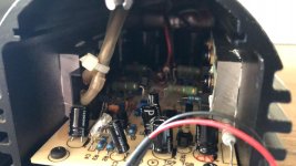
For some reason I didn’t take any photos with it opened up but it closely matches the schematic. Mine has “issue 4” on the PCB which is later than the shared schematic but the only difference is the zener diode “mod” isn’t there but that is drawn on the diagram so perhaps a non-factory mod.
I thought perhaps you had replaced other components such as the output transistors. I did find one capacitor was reading low (in circuit) and didn’t match the other amp but after removing from the pcb it did read as in spec. However I had already bought a set of caps so those were replaced anyway.
I thought perhaps you had replaced other components such as the output transistors. I did find one capacitor was reading low (in circuit) and didn’t match the other amp but after removing from the pcb it did read as in spec. However I had already bought a set of caps so those were replaced anyway.
This is literally the only pic I have or seen in regards to the thermal cut attached to heatsink. I will check online to see if I can find similar. A friend sent me that a long time back as he had a few pairs. I thought I knew of more mods in this version but I could have been wrong as I don't remember.
Not sure on Zener mod either and I have no idea what my version is. I will definitely dig it out when I get a chance as I'm really intrigued.
Again not sure on the output transistors but I don't remember it being original or TIP transistor. From my picture it looks similar to the picture below, I know that doesn't say much.
Attachments
You won't find manufacturer's part numbers on Musical Fidelity's power transistors. They systematically rubbed off the type (said to be TIP 35) and renumbered them with their house codes (that could be 152H, per the 03 schematic). There's good and not so good reasons for house codes that but they all add up to more expense than you might otherwise incur, if you knew the specification (if any) that might show any difference to standard Onsemi or STmicro product, straight out of the packing tubes.
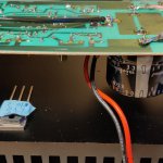
From the above pic, those transistors are the obsolete TO218 style, with exposed metal tab and similar to TO220 style. Current product is TO247 and fully enclosed, apart from the rear contact face.
From the above pic, those transistors are the obsolete TO218 style, with exposed metal tab and similar to TO220 style. Current product is TO247 and fully enclosed, apart from the rear contact face.
I appreciate the input! Still have my Arcam DAC to fix and a NAD C320. Both have been abandoned currently. You can thank my kids for that LOL
The output devices are the original style with the exposed metal top & isolation washer. The thermal cut off was not inside mine so might be a modification. The capacitors look original & match mine before replacement (the feedback cap is non polarised as per spec). My C4 capacitor is a green polystyrene item but probably just a different component batch.
It does but thermal protection needs to be chosen and tested carefully since its design will depend on the size of heatsinks, ventilation and the speaker efficiency which is related to how much power you are likely to dissipate before any sound is even audible. Couple that with the sensor's fixed range of cutout temperatures and you may have to think hard about where it should trip as you don't want it in normal use but it must trip well before there is a risk of second breakdown in the output transistors. You could also find that your amp was OK sitting atop a cabinet but soon shuts off when in your audio shelving and so on.
Last edited:
Hi,
hope it's fine to jump on this thread with all these knowledgable folks 🙂
A little history:
I am also in the process of restaurating an old pair of X-A50 of mine. Bought them around 1999, used them for 1-2 years, when they started making extremely loud thumps when being switched on. When on, they worked fine. But I stopped using them to not risk my speakers.
A friend of mine thought it would likely be caused by faulty capacitors and changed all of them, but no, wasn't fixed. Then they slept in my basement until another friend of mine triggered the electronics interest in me again recently (I had done mostly digital stuff until then, that's why I did not dare doing anything on the X-A50s before myself). I now thought, why not and pulled them out there weird hosuings and started measuring with my 40 year old Hameg scope.
At first I was not very successful, until I blew the output stage of one of them as a result of a dumb mistake. Step by step I replaced transistors and finally after replacing TR8, the amp was working again, and without the switch-on thump!
I then only replaced TR8 on the other X-A50 and the thump was gone too! The 2nd TR8 which I removed only showed hFE of 20 on a device tester. Never would have thought that they could go bad this strangely. But searching the net I found it is not uncommon. This happenign after only a short period of using the amps is still surprising to me.
As part of the restauration, I will move the amps into one full-size case as a dual mono, with more stuff, like speaker protection, 12V trigger etc.
My my question now is (bear with me for above babble, needed to get that out 😛:
With the case and heat sinks I already have, I would need to connect the power transistors with cables of about 3-5cm length. Would this be a problem? I guess the C and E lines wouldn't be a problem, but the B signal is pretty low (0.2mA according to LTSpice in idle). Can that cause more noise, or indirectly via NFB cause higher THD?
Thanks a bunch for any helpful advice,
Mo
Attachments
Last edited:
I would need to connect the power transistors with cables of about 3-5cm length. Would this be a problem?
There is no easy way of knowing. Stray pickup isn't an issue as such because the impedances are low anyway, what is an issue is the effect caused by the leads introducing parasitic inductance and capacitance and causing high frequency instability.
You will only know by trying. If you do try, then keep the leads away from each other as much as possible i.e., don't wrap them together.
Interesting! Patrick101 mainly helped me with this. I hope he still has his expertise to offer!
As part of the restauration, I will move the amps into one full-size case as a dual mono, with more stuff, like speaker protection, 12V trigger etc.
My my question now is (bear with me for above babble, needed to get that out 😛:
With the case and heat sinks I already have, I would need to connect the power transistors with cables of about 3-5cm length. Would this be a problem? I guess the C and E lines wouldn't be a problem, but the B signal is pretty low (0.2mA according to LTSpice in idle). Can that cause more noise, or indirectly via NFB cause higher THD?
1. as a dual mono amp, try making the whole amp layout symmetric
2, connect both amp ground with same wire length(as short as possible) to a single point to the chassis in between two amp board
3, the input RAC jack ground should not shorted to the case, the jack keep some distance from speaker terminals, the input jacket and cable should be closed to amp board as short as possible and avoid any speaker output wires crossing the input wires
4, connect the power transistors with cables of about 3-5cm length no problem, each B legs can connect to PCB with a 10 ohm 1/4W (or 1/2W) resistors(as protecttion), all C E legs wires can handle the output current and keep the same length, as short as possible for all power transistors
5. adding others stuff should take care the grounding which should be connected to the single point to the chassis same as the amp board
6. careful handle the AC input wires and power switch for safety, using the right Fuse rate
Happy building the new amp!
Hi Patrick, thanks for the advice. What is the purpose of 4.? In LTSpice, with or w/o does not seem to make a noticeable difference, so it seems it wouldn't harm. But I am not getting the intent.4, connect the power transistors with cables of about 3-5cm length no problem, each B legs can connect to PCB with a 10 ohm 1/4W (or 1/2W) resistors(as protecttion), all C E legs wires can handle the output current and keep the same length, as short as possible for all power transistors
EDIT: Same reason as grid stops on tube amps? Would somehow make sense.
Thanks, Mo
Last edited:
the resistor can protect the output transistor from over drive current, in normal condition it will not affect the amp
Hi, I am still in the process of rebuilding into a "real" case. All parts mostly ready now to be "married", X-A50 boards on heatsinks, protection boards, cap multiplier power supplies (I know, the amp should have proper PSRR, but simulating in Spice showed the ground noise to be sooo much lower with them compared to simple PSs, that I need to try) etc.
The other day, I stumbled upon a "gain structure" discussion. I checked and indeed the original gain of this amp seems to be overly high for my system. If I am not mistaken gain is defined by the ration of R9/R5, meaning it is over 30x.
I tried setting a higher value for R5 in Spice, which makes it easy to get the gain into the range of 10x, which would be much better, I think.
What I was wondering is if this changes the overall feedback. And if that was the case, I could get the same ratio with higher resistor values too. In Spice, the THD distribution and height does not change in a noticeable way when lowering the gain this way.
Any advice from folks being more knowledgeable than me?
Thanks,
Mo.
- Home
- Amplifiers
- Solid State
- Musical Fidelity X-A50 monoblock amp Circuit