Many thanks, cumbb. Kind of you to try and help. I have, I think, all the diagrams schematics etc. that are available. The problem is that I am not an electronics expert. I have changed capacitors, diodes and resistors but only where I suspected (from advice or visual avidence) that they were damaged by heat. I have had great success so far with the amps sounding fabulous.
But now it probably comes down to testing and the amp cannot be tested powered with the lid off as the amp is class A and the lid is the heat sink for the output transistors and they will (so I have read) fry in about 30 seconds.
Basically, I need to know what to try next. My guess is the transistors in the area that got hot so I am reading up on how to test them. Any other suggestions for a drop in HF?
Without a lot of measurerement-stuff and so on, I would start with the simplest, with the caps. Would change all in both, in the four;-) amps.
You will have much much more time to test. Not 30 sec. only. Do not worry;-)
You will have much much more time to test. Not 30 sec. only. Do not worry;-)
Aluminium extrusion off-cuts are often sold by the kilogram, so it may not be too expensive to fit a suitable shape such as a rectangular hollow section or a channel section vertically, as a substitute for the cover plate heatsink. Try not to exceed the width of the flange, which would obscure the PCBs and squeeze just enough thermal grease on the flange to wet the surfaces. A conductive type grease as used for CPU cooling would be OK here but don't use it for mounting semis.
You could probably clamp the extrusion rather than bolt it, which makes it a quick and easy job. You won't need a massive heatsink for the amount of time the power might be on for testing anyway. In any case, the top cover isn't exactly a big heatsink nor is oriented vertically to get much airflow for cooling anyway.
You could probably clamp the extrusion rather than bolt it, which makes it a quick and easy job. You won't need a massive heatsink for the amount of time the power might be on for testing anyway. In any case, the top cover isn't exactly a big heatsink nor is oriented vertically to get much airflow for cooling anyway.
That's a great idea, Ian. Thank you. I had briefly thought of that and if I fail to fix it by looking for bad connections/etc. and get desperate I will go that route. I have noted that there are some very different diodes in the power supply and I am wondering if they could make any significat difference. In the meantime I am trying to ensure both are using components close enough in spec not to cause this problem.
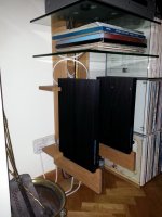
Incidentally, I normally run these amps mounted vertically to aid heat dissipation through natural air flow. I made a rack specifically for them.. here's a pic.
Incidentally, I normally run these amps mounted vertically to aid heat dissipation through natural air flow. I made a rack specifically for them.. here's a pic.
Attachments
Schematic MA-50/MA-50X ?
Who can upload a schematic of this monaural power amplifiers ?
Thank you very much.
P.S. maybe the schematic is close to one of the attached ones. This URL's don't provide the wanted information:
https://www.https://www.diyaudio.com/forums/solid-state/177572-musical-fidelity-1-class.html
Wierd behaviour-> Musical fidelity A100
Attachments
Last edited: