Good day all,
While there is a nice discussion about the Muses electronic volume control designed by our friend @meldano here, I am going to take the opportunity to document my build here for anyone considering doing the same. I wouldn't expect it to be a @6L6 quality build guide, but will follow my adventures while building this quality project.
Muses Volume
I'll be honest, I've grown lazy and find that devices without remote controls aren't as favorable as those with. So I went on a journey to discover VCs that supported remote controls. I found a few really nice ones, some less so. And then my friend @dBel84 suggested I take a look at the above Muses-based electronic attenuator project. Programmable features, input switching, remote control learning... I was hooked. So I reached out to @meldano and was able to secure a board set. After placing a parts order, I was ready to begin.
Since this is my first adventure with SMD devices, I practiced on an old circuit board with some leftover parts from other projects provided by a friend after watching hours of YouTube videos on the subject. Turns out it's not so hard.
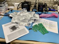
So I am starting with the Main Board (input switching, power supply) to get good at wide-pitched devices first. Between both boards I used a combination of soldering iron and hot air rework machine. Soldering iron is much faster if you have the right size and types of tips to work with. But the soldering paste and hot air are fun to watch do their magic, even if you're waiting several minutes for things to come to temperature.
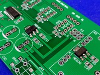
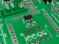
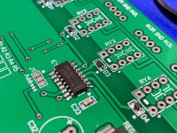
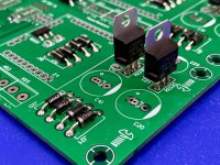
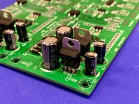
Thanks to @dBel84 for the suggestion to start with the larger components first. The rationale, which is a little different from conventional thought, is that larger parts require more heat to apply (if using hot air) and you're more likely to blow small parts off of their spots with the excess heat needed for larger ones. So I started with the larger LED driver chips and the power regulators.
Next step is to start placing the smaller SMD resistors and capacitors before moving to through-hole components.
Disclaimer: While I know what the device does, I'm not intimately familiar with how it does it outside of the high-quality documentation that @meldano provides in the above-linked post. I'm just following the directions and shooting for a working device when it's done. 🙂
I may deviate from the normal a little bit during this project. The preamp I have chosen to put this VC into uses the attenuator after the gain stage, and this one was designed to go before the gain stage. The input switching circuits feed into the attenuator stage, and then the output is meant to feed whatever gain stage you have. So I will be deviating from the plans a little bit to separate the components in a way that will allow it to work that way.
Typical:
Kit Input Switching > Kit Muses Attenuator >Preamp Gain Stage
My configuration:
Kit Input Switching > Preamp Gain Stage > Kit Muses Attenuator
I've figured how to do this without too much issue, but for purposes of this discussion I'm just going to build it so you can see how it goes together.
Enjoy!
~Chris
While there is a nice discussion about the Muses electronic volume control designed by our friend @meldano here, I am going to take the opportunity to document my build here for anyone considering doing the same. I wouldn't expect it to be a @6L6 quality build guide, but will follow my adventures while building this quality project.
Muses Volume
I'll be honest, I've grown lazy and find that devices without remote controls aren't as favorable as those with. So I went on a journey to discover VCs that supported remote controls. I found a few really nice ones, some less so. And then my friend @dBel84 suggested I take a look at the above Muses-based electronic attenuator project. Programmable features, input switching, remote control learning... I was hooked. So I reached out to @meldano and was able to secure a board set. After placing a parts order, I was ready to begin.
Since this is my first adventure with SMD devices, I practiced on an old circuit board with some leftover parts from other projects provided by a friend after watching hours of YouTube videos on the subject. Turns out it's not so hard.
So I am starting with the Main Board (input switching, power supply) to get good at wide-pitched devices first. Between both boards I used a combination of soldering iron and hot air rework machine. Soldering iron is much faster if you have the right size and types of tips to work with. But the soldering paste and hot air are fun to watch do their magic, even if you're waiting several minutes for things to come to temperature.
Thanks to @dBel84 for the suggestion to start with the larger components first. The rationale, which is a little different from conventional thought, is that larger parts require more heat to apply (if using hot air) and you're more likely to blow small parts off of their spots with the excess heat needed for larger ones. So I started with the larger LED driver chips and the power regulators.
Next step is to start placing the smaller SMD resistors and capacitors before moving to through-hole components.
Disclaimer: While I know what the device does, I'm not intimately familiar with how it does it outside of the high-quality documentation that @meldano provides in the above-linked post. I'm just following the directions and shooting for a working device when it's done. 🙂
I may deviate from the normal a little bit during this project. The preamp I have chosen to put this VC into uses the attenuator after the gain stage, and this one was designed to go before the gain stage. The input switching circuits feed into the attenuator stage, and then the output is meant to feed whatever gain stage you have. So I will be deviating from the plans a little bit to separate the components in a way that will allow it to work that way.
Typical:
Kit Input Switching > Kit Muses Attenuator >Preamp Gain Stage
My configuration:
Kit Input Switching > Preamp Gain Stage > Kit Muses Attenuator
I've figured how to do this without too much issue, but for purposes of this discussion I'm just going to build it so you can see how it goes together.
Enjoy!
~Chris
Attachments
Last edited:

The quality of your first attempts at SMD puts my early efforts to shame 
looking forward to watching the evolution of this project and the final choices for preamp
..dB
looking forward to watching the evolution of this project and the final choices for preamp
..dB
Wrapped up the SMDs on the main boards this morning (two required for balanced applications). Those parts sure are tiny! The diodes were a hoot to work with. Since they have little tiny feet, they don't necessarily lay flay after working them with a hot air machine like the caps and resistors do. So after I got them attached, I applied flux, went back with the micro-chisel tip on my iron, provided some top pressure with tweezers, and reflowed the pad while gently massaging the diodes into a better position. Yes, they would have worked just fine. But I prefer them to be as flat on the board as possible. Went back with a multimeter and made sure none of the components were shorted beneath. All good.
Attachments
Last edited:
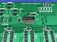
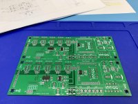
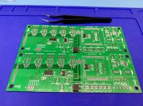
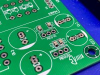
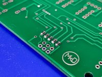
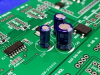
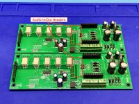
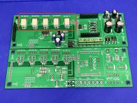
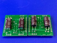
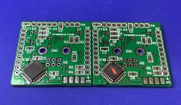
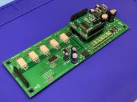
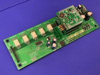
Finished up the main boards today. I've not yet installed some of the headers as I have yet to figure out exactly how I'm going to integrate it into my preamp. The X3 and X4 connectors circled in the images below are responsible for moving the audio signal in and out of the volume attenuator boards from the main board. As mentioned earlier, this device is designed to go before the amp/buffer. Since my preamp uses this volume control after the amp/buffer, but still keep the input switching before it, I need to split the setup in two, and this is where the signals need to be extracted for that (X4, specifically). So once I design exactly how that's going to work with my setup, I'll determine how those last two 3-pin connections will be utilized.
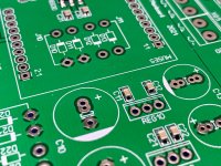
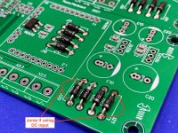
The euro connectors accept the input from the power supply(s). It's actually quite a smart circuit because you can send it either AC or DC. If you send it AC, there's a bridge rectifier in the circuit to do the conversion. If you send it DC from an outboard supply, leave the diodes off the board and install a couple of jumpers per circuit to feed DC in. Linear regs down stream massage the final circuit voltages.
Next up, Volume Control boards.
Attachments
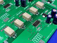
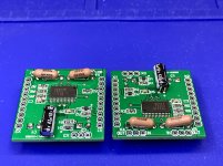
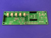
Turns out I "overbuilt" one of the boards. If used in a balanced configuration, you only need the switching devices and the connection risers on the second board (p.13 of the documentation--I overlooked it). So the power supply components are redundant.
Thankfully I have a third board so I can build that one up with those parts. Now I can use this board in a separate single-ended project. 🙂
Thankfully I have a third board so I can build that one up with those parts. Now I can use this board in a separate single-ended project. 🙂
Attachments
Very nice clean work Chris, also interested in what gain stage you choose, Wayne's BAF linestage would be good depending how much gain you need. Simple diamond buffers work very well on the Muses output.
Thanks a million. 🙂 Right now my choice is Aleph P. It tends to be pretty high gain, though, even though you can tune it down. When I called NJR, they said Muses will handle 10V on the inputs without issue, so we'll see how it goes.
Appreciate the line stage suggestion. It seems highly regarded. Others have suggest Iron Pre as well. Reckon I'll play it by ear (so to speak). 😀
Appreciate the line stage suggestion. It seems highly regarded. Others have suggest Iron Pre as well. Reckon I'll play it by ear (so to speak). 😀
Very nice clean work Chris, also interested in what gain stage you choose, Wayne's BAF linestage would be good depending how much gain you need. Simple diamond buffers work very well on the Muses output.
For a newbie, this guy acts like a pro. Notice the blue ESD pad he has; notice the soldering gear, the hot air rework station, etc...
There is no need for sloppy work even for newbies!
Very classy. Well done.
Best,
Anand.
There is no need for sloppy work even for newbies!
Very classy. Well done.
Best,
Anand.
Looking forward to the updates. I'm not a big fan of soldering SMD parts. It has been hit or miss for me, but looks like your doing a great job.
Do you need the gain stage? Or is that a separate device that the builder provides?
Do you need the gain stage? Or is that a separate device that the builder provides?
Last edited:
For a newbie, this guy acts like a pro. Notice the blue ESD pad he has; notice the soldering gear, the hot air rework station, etc...
There is no need for sloppy work even for newbies!
Very classy. Well done.
Best,
Anand.
Thanks Anand 🙂 I worked on fighter jet electronics in the Navy, so there's something engrained into me about using the right stuff safely. But it's great fun (and a relief) knowing that what I'm building here isn't required to stay in the air!
Looking forward to the updates. I'm not a big fan of soldering SMD parts. It has been hit or miss for me, but looks like your doing a great job.
Do you need the gain stage? Or is that a separate device that the builder provides?
SMD is new for me. It's been an experience, no doubt! YouTube has been a saving grace for this project.
This is the functional equivalent of your normal volume control. It doesn't need a gain stage if you don't want it. If you're planning on doing the equivalent of a passive attenuator, nothing else is really needed. If you need a buffer or gain stage, then the builder provides that.
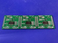
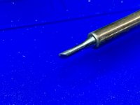
Started on the volume attenuator boards today and got the Muses 72323 chips soldered on. I started with the hot air machine. Soldering paste is a bit of a dark art getting it applied just right, especially with these fine-pitched devices. There was a bit too much paste and it resulted in some bridging. So with a bit of massaging with flux, some desoldering braid, and whatever kind of tip this one is called, I removed the excess solder and cleaned everything up. I see that there's a reservoir version of this tip, but mine's just flat.
Second and third boards I used only the soldering iron. Much easier to work on that way. That and my 3x reading glasses and a desktop magnifier. 😛 Rang everything out with a meter. No bridging and all checks good.
In case I didn't mentioned it earlier, I happen to have three of everything since I'm building a balanced set for myself and an unbalanced set for a friend.
Attachments
Last edited:
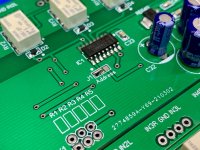
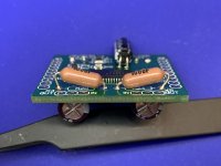
Finished soldering the components on the Volume Attenuator Boards this evening. Waiting on some Arduino-style risers to arrive so I can get the stacking process right. All the boards piggy-back onto one another and share a parallel power supply bus. My affinity for those slick Dale resistors got the best of me and they're a little large for their provided component spacing. So they're tilted up a bit to fit into the space and provide clearance from the adjacent connector strip.
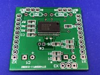
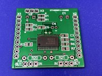
An interesting thing about these Volume Attenuator Boards in a balanced configuration is the Muses chips are addressed separately by the microcontroller. Under one of the caps on the back side of the board is a set of jumpers. Jump one pair of pins if this board is destined to be left channel and the other pair for right. You can see it circled in the photo. Apologies for the fuzzies left behind by the cleaning crew.
Also soldered the controller chip on the Microcontroller Board as well. Working tomorrow night, so I'll probably not get to the rest of the devices on the micro board until Friday. It's okay, though. It's going to take a few more days (at least) for the supply house to process my most recent order.
Attachments


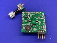
Finished up the uController board tonight. As luck would have it when you have dozens of choices of parts, I chose the wrong encoder. This one has a push-on/push-off switch instead of a momentary type. So another order went into the parts store tonight. If I got it right this time, the part number should be Alps EC11E15244B2. That’s a 15/30 encoder with momentary push switch. Lesson learned, read the spec sheet over trusting the product description on the supplier’s web site. 🙂
Ditto with pin headers. With thousands of choices, pretty easy to buy the wrong part. I thought I got 90° headers, but they were straight. So now there’s a wait for them, too.
It’s cool, though. Have other things to work on while waiting.
Ditto with pin headers. With thousands of choices, pretty easy to buy the wrong part. I thought I got 90° headers, but they were straight. So now there’s a wait for them, too.
It’s cool, though. Have other things to work on while waiting.
Attachments
Thanks dB. 🙂 It's been a learning experience! Looking forward to seeing (hearing) it work in an actual audio device!
It is all looking so good! Exceptional work.
.. dB
Last edited:
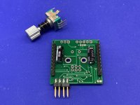
Received another collection of parts yesterday and was able to (mostly) complete the unbalanced version of the volume control. Still waiting on some 90º headers and the proper encoder to arrive. Sneaking up on it!
I won't install the input, output, and LED terminations until my friend and I determine how they're to be connected in his particular preamp project (dualing preamps, he and I).
I won't install the input, output, and LED terminations until my friend and I determine how they're to be connected in his particular preamp project (dualing preamps, he and I).
Attachments
Last edited:

- Home
- Source & Line
- Analog Line Level
- Muses Electronic Volume Control Build from Wisconsin