Thanks! I’ll get on it.
- check the I2C pull ups values (R5,6 controller board)
- the controller should switch off/on after setting the max in parameter
- disconnect the leds from the main board
- ic1 direction (main board) is correct?
- check ic1 3V3 supply
Last edited:
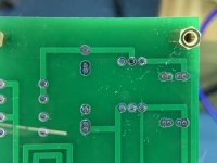
I tracked down one problem this evening: the missing -15VDC on the balanced board set. I started systematically disassembling things until voltages were restored. Once the voltage came back, I found the culprit was the second unpopulated board (except relays). I measured across the -15V capacitor spot and it was dead shorted.
After analyzing everywhere -15VDC was routed on the board, I noticed that a wave soldering glitch from the board manufacturer that bridged all the -15V regulator pads together as well as a little splashing in a couple other spots. Little bit if desoldering wick and problem solved. No more short.
One step closer to getting it working!
Attachments

Now that voltages are all correct, I tried my "working" uController board on both the single-end and balanced configurations and the reactions are the same: no main board switching actions. Since the boards layer together with I2C connections, I was able to remove the Volume Control board from the stack and still be able to test connectivity between the uC and Main boards. One less distractor in the equation. Still not working correctly. So I may have installed something incorrectly on my uC board. I'll be double-checking all components to make sure they're right for the spot, oriented correctly, looking for solder bridges, etc.
My first SMD project, so there are certainly things to learn. Probably my first mistake was to build two of the same in parallel instead of learning from one before building the other. I recommend working on one at a time. 🙂
My first SMD project, so there are certainly things to learn. Probably my first mistake was to build two of the same in parallel instead of learning from one before building the other. I recommend working on one at a time. 🙂
Please check the I2C (SDA/SCL) connection between the controller and ic1 on the mainboard.
Double check the max input parameter is grater than 0 and reboot.
Daniel
Double check the max input parameter is grater than 0 and reboot.
Daniel
Please check the I2C (SDA/SCL) connection between the controller and ic1 on the mainboard.
Double check the max input parameter is grater than 0 and reboot.
Daniel
Will check again, thanks. When I checked last night, SDA was static high (+5V), and SCL was static high (+3.3V), on both the I2C and IC1. So the connectivity is good and rings out to zero ohms between. Pull up resistors both measure 2.7K as specified. I prayed that I didn't install IC1 upside down, but it appears correct. I tested the output LED drivers with my multimeter on a spare IC1 that I had and verified that I had it installed correctly. Max input is set to four (4).
Last edited:
After checking one of my uController boards that had a low 3.3V power supply (down to a little over 1.5V, I decided to remove the micro and check for solder quality beneath the controller chip. All was well. So I used some braid and cleaned up the area and soldered the chip back in. Same result as previous, so the chip may have been damaged either during install (overheated with hot air gun) or maybe it got zapped when my previous transformer gave up.
The devices seem to be on a pretty significant back order worldwide, so I’ll have to get creative with sourcing. Keeping fingers crossed for a manufacturer’s miracle. 🙂. If I can get a couple, I’ll replace the one in my other board set as well for good measure.
@meldano has a few, but I’d rather he provide those to new builders if I find another avenue for the chips. No need for my build to penalize others in need.
This time I’ll solder them in with an iron instead of a heat gun. Try to keep the hot stuff away this time around. 🙂
I ordered new microcontrollers from @meldano to correct the one problem child and a "just in case" device. Daniel went out of his way to find replacement devices for me since they're on worldwide backorder right now. For that I am ridiculously thankful!
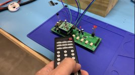
They arrived late last week and I had the opportunity to replace the one damaged device and the voltages popped back up to where they should be. Problem #1 resolved! I powered up the volume control and it came on without issue. It accepted the remote control codes as expected. Another victory! However, it still failed to switch the relays on the main board.
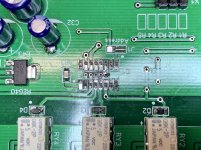
I checked the continuity of traces between the microcontroller board and the main board and all was well there. I checked the voltages again, just as I had many times before, and something just seemed off. They were the same voltages I'd read in the past, but this time something clicked that I needed to check. One pin read +5V where it should have read +3.3V. I didn't see it as a problem before, but today I did. So I asked myself, "What are the chances?" So I desoldered my LED/relay driver chip to investigate beneath it. Oh my word...
Total n00b SMD/airgun/solder paste mistake. Not enough heat, not long enough, too much paste... There were bridges all over the dang place causing the driver chip to be unable to do its job. Man, do I feel dumb! Time to check my other ones!
Now, I'm happy to say that my unbalanced set is switching great, just as it's supposed to. Time to get some sound through it and see how the volume control side works!
Embarrassing solder job photo and success photo below. Moving forward!
They arrived late last week and I had the opportunity to replace the one damaged device and the voltages popped back up to where they should be. Problem #1 resolved! I powered up the volume control and it came on without issue. It accepted the remote control codes as expected. Another victory! However, it still failed to switch the relays on the main board.
I checked the continuity of traces between the microcontroller board and the main board and all was well there. I checked the voltages again, just as I had many times before, and something just seemed off. They were the same voltages I'd read in the past, but this time something clicked that I needed to check. One pin read +5V where it should have read +3.3V. I didn't see it as a problem before, but today I did. So I asked myself, "What are the chances?" So I desoldered my LED/relay driver chip to investigate beneath it. Oh my word...
Total n00b SMD/airgun/solder paste mistake. Not enough heat, not long enough, too much paste... There were bridges all over the dang place causing the driver chip to be unable to do its job. Man, do I feel dumb! Time to check my other ones!
Now, I'm happy to say that my unbalanced set is switching great, just as it's supposed to. Time to get some sound through it and see how the volume control side works!
Embarrassing solder job photo and success photo below. Moving forward!
Attachments
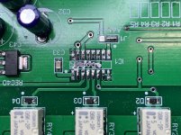
I must say, the second one (balanced set) was just a bad as the first! Cleaned it up, resoldered the driver chip, and all works well. This one doesn't want to come out of mute very easily without forcing it in/out of mute when changing inputs. This may be because I've got some jumpers out for Aleph P use. I'll double check that. It may be the system's way of protecting itself from the like of me. 🙂
FYI, when switching inputs, this system goes:
MUTE --> SWITCH --> UNMUTE
Keeps switching noise, pop, clunk to a minimum.
Another embarrassing SMD n00b photo:
FYI, when switching inputs, this system goes:
MUTE --> SWITCH --> UNMUTE
Keeps switching noise, pop, clunk to a minimum.
Another embarrassing SMD n00b photo:
Attachments
Just an FYI, we were ALL newbies at one point 🙂
I must point out that I think your work is very nicely done and neat.
The solder-paste and hot air thing...it comes with experience, I'm willing to bet everyone here doing that sort of stuff has made atleast as embarrassing mistakes as you in the past.
Keep up the good work, and welcome to the world of SMD's(I'm more comfortable with those these days than THT parts).

Appreciate the feedback. Always improving my processes! First go at SMD. Every component I put down gets a little better.
Hi, what is the difference in function between the status LED on the controller board and the status led on the relay board? The status LED on the controller board needs to be visible in the front panel for feedback when setting parameters.
The LED signal refered to in Parameter 7 in the parameter table on page 4/23, is this the LED from the relay board?
Kind regards
The LED signal refered to in Parameter 7 in the parameter table on page 4/23, is this the LED from the relay board?
Kind regards
I finally got my setup in a condition I can test it. Exciting day!

After a lot of futzing, I cannot get the left (bottom) side to work (balanced set). I even reset the MCU and reprogrammed everything from zero. Same thing.
Conditions:
* Both VA boards work. I can swap positions and sound goes through, but only when in the top position. Lower position has no output.
* VA boards are jumpered properly, J2-1/2 on one, J2-2/3 on the other.
* Switching relays are working on both main boards.
* Programmed for balanced operation: Parameter 8=001
* Programmed for four inputs: Parameter 4=004
* VA board X4-1, X5-1 show input signal; X4-3, X5-3 show no output signal. But only in the bottom position. Works fine in top position.
I’ve traced everything I can think to trace that is reachable from the outside. Happy to hear anyone’s ideas!
Schematic: https://1drv.ms/b/s!AspuupI-wTK0grodEXg8HN22YXi-ew?e=AtmMCW
~Thanks
Last edited:
* Both VA boards work. I can swap positions and sound goes through, but only when in the top position. Lower position has no output.
Sorry.
Please check all signal traces on mainboard.
For example with sine wave.
Please check all signal traces on mainboard.
For example with sine wave.
Will do. I did an initial check with music playing and AC on my multimeter until I stopped seeing voltage. But I will set up a more detailed check with an o’scope.
- Home
- Source & Line
- Analog Line Level
- Muses Electronic Volume Control Build from Wisconsin