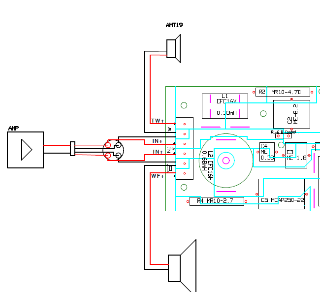
Point being, Erik, that that is DEFINITELY not a series crossover:
I could probably guess the rest of the components. Impedance correction.
Here's the thing. Despite all your Accuton and Scanspeak theories about 6" drivers. They still have that horrible peak around 4-5kHz along with tonal inaccuracies. 4 ohm is easier for sure.
I mean, I could come up with all sorts of theories about the perfect speaker, but in the end, all is compromise. It's built into the Universe. But for all that, I would do the expensive patented components if I could. 🙂
Attachments
Thanks Steve! 🙂
That was what I also wanted to say. No way the boards and images match up with the 1st order anything. 🙂
Best,
Erik
That was what I also wanted to say. No way the boards and images match up with the 1st order anything. 🙂
Best,
Erik
Point being, Erik, that that is DEFINITELY not a series crossover:
I could probably guess the rest of the components. Impedance correction.
Here's the thing. Despite all your Accuton and Scanspeak theories about 6" drivers. They still have that horrible peak around 4-5kHz along with tonal inaccuracies. 4 ohm is easier for sure.
I mean, I could come up with all sorts of theories about the perfect speaker, but in the end, all is compromise. It's built into the Universe. But for all that, I would do the expensive patented components if I could. 🙂
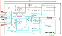
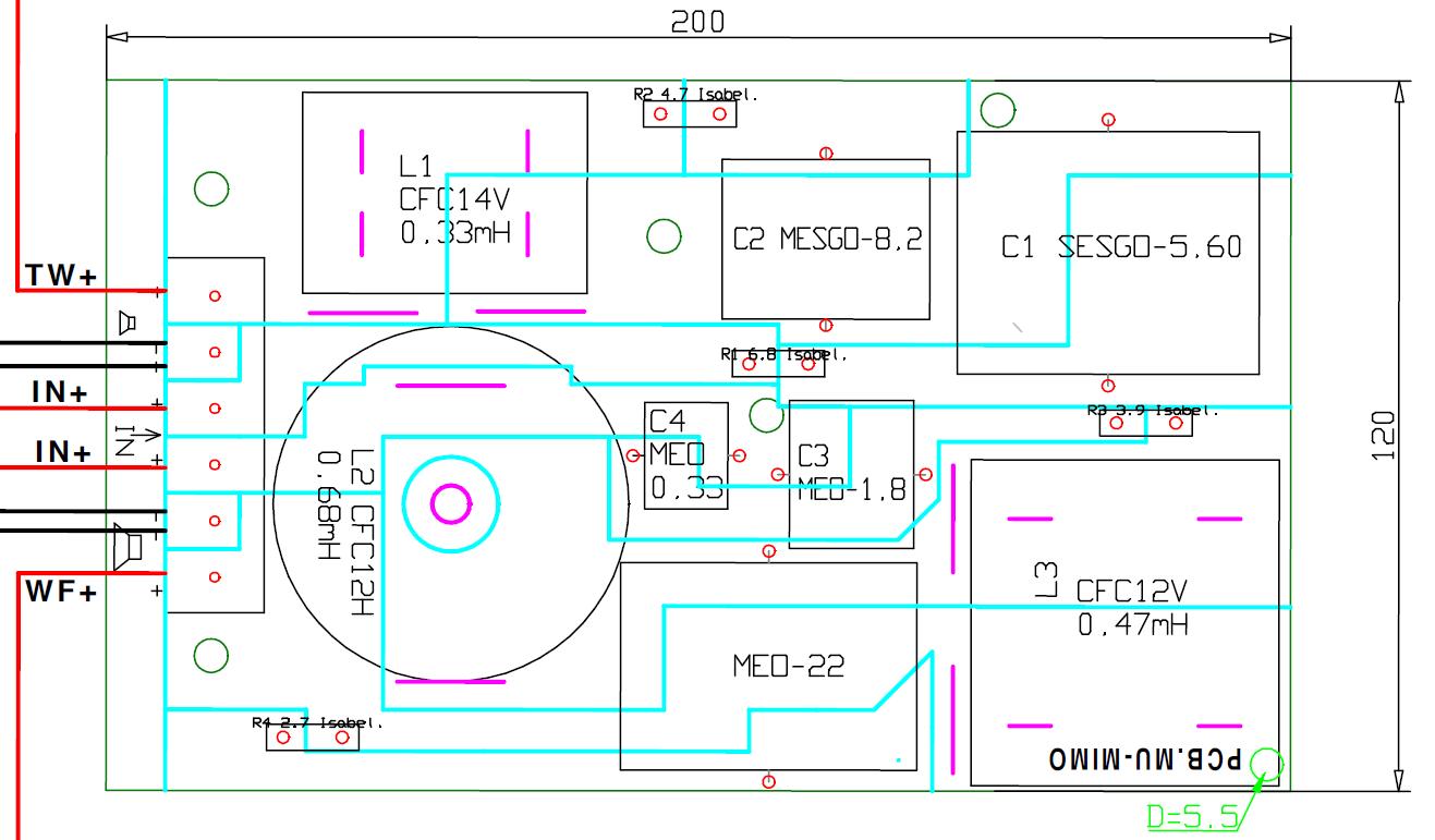
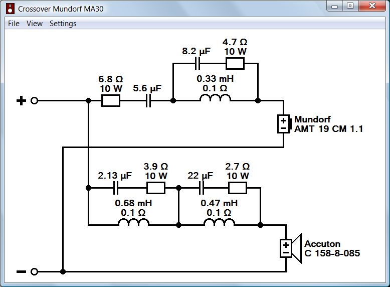
Based on the pcb I come to the conclusion that Mundorf's description of the crossover is fully correct. First order with notches and without any parallel components.

Hi Dissi,
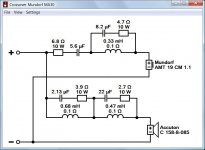
Looks good but I think there is a difference from the board picture you are using and what I used. On the tweeter HP section, the cap immediately after the 6.8 Ohm resistor appears to be 6.8 uF in pictures I've seen of delivered crossovers as well as the diagram I am using, which comes from p. 14 here: http://www.mundorf.com/PDF/Mundorf_MA30_Catalog.pdf
I do not however have any justification for avoiding parallel components. I always thought it was parts in series with the drivers that were to be avoided. What an interesting shtick.
Best,
Erik
Last edited:
Or, it's easier to see here, page 2:
https://shop.grantfidelity.com/files/MA30%20Kit%20Drawings%20and%20Set%20Up%20Reccomendation.pdf
https://shop.grantfidelity.com/files/MA30%20Kit%20Drawings%20and%20Set%20Up%20Reccomendation.pdf
Based on the pcb I come to the conclusion that Mundorf's description of the crossover is fully correct. First order with notches and without any parallel components.
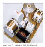
Gadzooks, the XO parts cost must be approaching the driver cost that all adds up to the $1759! What was Mundorf thinking?????????
Awful pile of spaghetti to untangle there... 🙁
There's something wrong looking about the 4.7R and 91dB tweeter level here, but I think I've mostly cracked it. Took me an hour!
Near 4kHz tank notch on third order bass filter. 3rd order tweeter too. The Accuton bass is about 0.6mH Le, the Mundorf is something like 8 ohms flat impedance and FR. Gotta be positive polarity on a 2kHz crossover.
Maybe just me, but I find something disturbing about the photo. 😱
Attachments
Well, OK fine then. Since no one else feels it's wrong to reverse engineer it and post with values, allow me to contribute what I had come up with for my blog post. 🙂
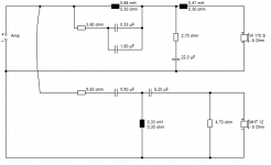
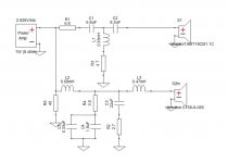
I took the FRD and impedance data for the drivers, used SPL copy, then used OmniMic to phase restore the generated driver FRD plots. Imported the driver ZMA and FRD into XSim before attempting to reverse engineer the board drawing I had in front of me.
Using that information, and guessing that the phase matching would be pretty close to ideal I came up with this schematic. This design yields perfect phase matching with -0.04" adjustments to the woofer distance (meaning woofer is 0.04" closer than tweeter), along with nearly ideal FR and quite usable impedance. R5 is my own invention though, I was playing around with damping the impedance peak. Please ignore it.

Please note the value of C1! There are at least two versions of the board drawing in the wild (and the Internet is quite wild) which use different values of C1 and possibly different layouts. All the pictures (not drawings) of the assembled crossover show C1 as being 6.8uF, so that's the board I am working off of. I am not responsible for the other one working out or not.
It's definitely possible that I made a mistake, but as I mention, the results say this is a nearly ideal crossover, so either I have found an alternate crossover by jumbling up all the same parts, or this is the actual design.
I'm even going to be so nice as to post a zip of the XSim file.
It is of course possible I just invented a new crossover in which case you can name your first twins after me.
Best,
Erik
I took the FRD and impedance data for the drivers, used SPL copy, then used OmniMic to phase restore the generated driver FRD plots. Imported the driver ZMA and FRD into XSim before attempting to reverse engineer the board drawing I had in front of me.
Using that information, and guessing that the phase matching would be pretty close to ideal I came up with this schematic. This design yields perfect phase matching with -0.04" adjustments to the woofer distance (meaning woofer is 0.04" closer than tweeter), along with nearly ideal FR and quite usable impedance. R5 is my own invention though, I was playing around with damping the impedance peak. Please ignore it.
Please note the value of C1! There are at least two versions of the board drawing in the wild (and the Internet is quite wild) which use different values of C1 and possibly different layouts. All the pictures (not drawings) of the assembled crossover show C1 as being 6.8uF, so that's the board I am working off of. I am not responsible for the other one working out or not.
It's definitely possible that I made a mistake, but as I mention, the results say this is a nearly ideal crossover, so either I have found an alternate crossover by jumbling up all the same parts, or this is the actual design.
I'm even going to be so nice as to post a zip of the XSim file.
It is of course possible I just invented a new crossover in which case you can name your first twins after me.
Best,
Erik
Attachments
Last edited:
Hi Dissi,
Looks good but I think there is a difference from the board picture you are using and what I used. On the tweeter HP section, the cap immediately after the 6.8 Ohm resistor appears to be 6.8 uF in pictures I've seen of delivered crossovers as well as the diagram I am using, which comes from p. 14 here: http://www.mundorf.com/PDF/Mundorf_MA30_Catalog.pdf
It's 6.8 uF on page 14 and 5.6 uF on page 16. Seems they used an old version in one of the two figures. Can you model both and compare them?
erik,
If your drawing is correct, this is an infinite slope crossover. Of all the different styles of parallel crossovers I tried, this was the most 'true to life' to my ears. If I am not mistaken, this is Joseph Audio's crossover of choice.
From what I've read, Jeff Bagby's quasi second order 2-way series crossover (balanced 2-way) may be more musical. Had I known of Jeff's crossover a few years ago, I could have saved myself hundreds of hours, and thousands of dollars finding mine, and just used his.
Well, OK fine then. Since no one else feels it's wrong to reverse engineer it and post with values, allow me to contribute what I had come up with for my blog post. 🙂
I took the FRD and impedance data for the drivers, used SPL copy, then used OmniMic to phase restore the generated driver FRD plots. Imported the driver ZMA and FRD into XSim before attempting to reverse engineer the board drawing I had in front of me.
Using that information, and guessing that the phase matching would be pretty close to ideal I came up with this schematic. This design yields perfect phase matching with -0.04" adjustments to the woofer distance (meaning woofer is 0.04" closer than tweeter), along with nearly ideal FR and quite usable impedance. R5 is my own invention though, I was playing around with damping the impedance peak. Please ignore it.
Please note the value of C1! There are at least two versions of the board drawing in the wild (and the Internet is quite wild) which use different values of C1 and possibly different layouts. All the pictures (not drawings) of the assembled crossover show C1 as being 6.8uF, so that's the board I am working off of. I am not responsible for the other one working out or not.
It's definitely possible that I made a mistake, but as I mention, the results say this is a nearly ideal crossover, so either I have found an alternate crossover by jumbling up all the same parts, or this is the actual design.
I'm even going to be so nice as to post a zip of the XSim file.
It is of course possible I just invented a new crossover in which case you can name your first twins after me.
Best,
Erik
Nice simmed FR Erik. Now, how does it sound?
How does 2 3rd order XO's with woofer response peak attenuation circuits become an infinite slope XO design?
Nice simmed FR Erik. Now, how does it sound?
How does 2 3rd order XO's with woofer response peak attenuation circuits become an infinite slope XO design?
Thanks SD!!
I thought you were asking me that question! Hahaha. 🙂 I'm with you, it's basic 3rd order stuff here.
I have only heard the speakers 1 time in a very very bad environment, so I can't give them a good review in that sense.
Best,
Erik
erik,
If your drawing is correct, this is an infinite slope crossover. Of all the different styles of parallel crossovers I tried, this was the most 'true to life' to my ears. If I am not mistaken, this is Joseph Audio's crossover of choice.
From what I've read, Jeff Bagby's quasi second order 2-way series crossover (balanced 2-way) may be more musical. Had I known of Jeff's crossover a few years ago, I could have saved myself hundreds of hours, and thousands of dollars finding mine, and just used his.
Billy,
Huh? Like SD points out, and I've mentioned before, this is simple 3rd order stuff with a little phase correction in the bass. Please see my blog here for a refresher. Where did you connect any of this to Joseph Audio's patented and complicated crossover designs? The identifying feature of those are the transformer-like coupled coils which is not to be found in these schematics.
Best,
Erik
Last edited:
Using a 5.6 uF cap at C1 is a modest change, but enough to disrupt the phase alignment and deepen the response at the crossover point just a smidge. Honestly don't think most would be able to hear the difference if that is the only change. If the rest of my analysis is correct then I would say 6.8uF should be the better choice.
Best,
Erik
Best,
Erik
Guys, please take a look at the Mundorf docs again. I think the schematic in post 23 is spot on. The schematics in posts 27 and 28 differ quite a bit from the PCB shown in the Mundorf docs.
Guys, please take a look at the Mundorf docs again. I think the schematic in post 23 is spot on. The schematics in posts 27 and 28 differ quite a bit from the PCB shown in the Mundorf docs.
I think it would be helpful to see post 23 simulated. Since I have posted the XSim, anyone who wishes to and has access to Windows should be able to quite easily. It's beyond my level of interest though.
The only things I really had to guess at was the ground location. Once I select those, the schematic came together pretty easily.
It would be pretty remarkable if post 23 had as good an outcome as the one I posted. Makes me wonder what the point is.
In any event, this is all just for fun. We shouldn't get too involved in this analysis, it's not as if we are launching the Hubble and must be sure the mirror is ground correctly. 🙂
Perhaps some one will send me a real board to trace. 🙂
Best,
Erik
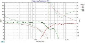
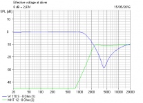
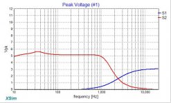
Just to make it easier, here's the FR with phase and individual drivers plotted. I'd be quite happy with a crossover like this. May not be right, but would be interesting to see if the convolutions needed to avoid paths to ground add anything, or if in fact we can just move the end points around and get the same results. 🙂

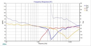
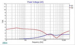
OK, I'm being completely OCD here. I used Dissi's schematic and the driver FR's are just not believable. The important part is the yellow line. Notice how poorly the individual driver responses match up compared to my original schematic. Now we have the smallest AMT tweeter crossing over around 2 kHz (not likely!) and the woofer at around 3-4kHz.
What are the chances that I would come up with such a neatly tuned crossover if I was so off?

I have posted the XSim schematic I used to reinterpret Dissi's hypothesis in case I blundered. Dissi makes a fine simulation tool as well, so I look forward to his contributions. 🙂
I would probably ignore the system/phase matching issues as they are based on my original hypothesis that the driver acoustic distance was near zero. The woofer FR is the real key I think. It's god-awful. Did my simulation miss something?
Best,
Erik
What are the chances that I would come up with such a neatly tuned crossover if I was so off?
I have posted the XSim schematic I used to reinterpret Dissi's hypothesis in case I blundered. Dissi makes a fine simulation tool as well, so I look forward to his contributions. 🙂
I would probably ignore the system/phase matching issues as they are based on my original hypothesis that the driver acoustic distance was near zero. The woofer FR is the real key I think. It's god-awful. Did my simulation miss something?
Best,
Erik
Attachments
Last edited:
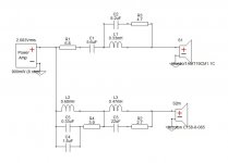
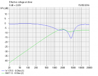
Finally, let's compare transfer functions for each hypothesis. First, the one I presented (voltage increased for clarity):

Looks absolutely mundane, boring, typical. Exactly what I might expect from a 2-way speaker system. Chances of me getting this so good while having completely wrong schematic: 1 to 1,000,000. Not impossible. I can imagine in some situations the same parts could be turned around and used in more than one way, but wow.
Now we compare Dissi's Hypothesis from post 23:

Nough said. Anyone who wants to gripe, please present the FR and phase plots to back it up. 😀 😀 😀
Best,
Erik
Looks absolutely mundane, boring, typical. Exactly what I might expect from a 2-way speaker system. Chances of me getting this so good while having completely wrong schematic: 1 to 1,000,000. Not impossible. I can imagine in some situations the same parts could be turned around and used in more than one way, but wow.
Now we compare Dissi's Hypothesis from post 23:
Nough said. Anyone who wants to gripe, please present the FR and phase plots to back it up. 😀 😀 😀
Best,
Erik
Attachments
This is all a pain IMO.
Dissi has interpreted the crossover correctly IMO. Some variation on 5.6uF or 6.8uF.
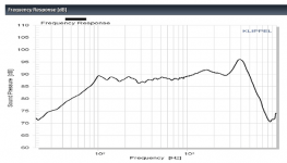
This is the unfiltered accuton woofer response, hence the 4kHz notch. The tweeter is flat.

But it all makes little sense to me. Polarity seems wrong for one thing. But one of those transient perfect speakers, I suppose.
Dissi has interpreted the crossover correctly IMO. Some variation on 5.6uF or 6.8uF.
This is the unfiltered accuton woofer response, hence the 4kHz notch. The tweeter is flat.
But it all makes little sense to me. Polarity seems wrong for one thing. But one of those transient perfect speakers, I suppose.
Attachments
Last edited:
- Status
- Not open for further replies.
- Home
- Loudspeakers
- Multi-Way
- Mundorf Accuton Kit - In Theory