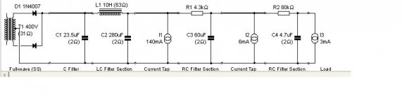
Schematic and PSUD model of power supply attached. Please comment/critique.
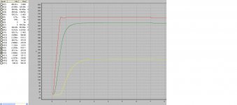
The 520V B+ is driving series stacked filter caps. The PSUD model has the KT88's at 70ma each, and the 12AT7 at 6 ma (total), and the EF86 at 3 ma. The 520B+ ripple voltage is around 20 mv.
The transformer is a Triode Electronics P782 S (400-0-400 @ 200ma, 60V bias tap, 6.3VCT @ 5A, 5V @ 3A) which is a Dynaclone MkII/MkIII transformer.
Eli: Hopefully I have the "hash filter" and the CL150 in the correct loaction.
Attachments
That was alot of work! Complete with snubbers, and hash filter too! Very nice, but why did we go back too the higher B+ voltages?
but why did we go back too the higher B+
Because I thought you wanted a higher B+ based on your posted schematic......

If you stay around 460-480V for B+, you won't need to double up the caps, which saves $$ and space.
Yeah I need to alter the schematic. Those high voltages were labeled by the orginal builder. i'll change it now unless there is any good reason to keep it that high. I did want the 60w output, but not if it is going to compromise sound, or reliability. Any defenders here of the high voltage? If not, i'll finalize the BOM for the PS. Thats a major hurdle out of the way, and it's really comming together now!
BTW. I hope this build will be of help to future builders. As you know there are many new people that come to the forum looking to build a basic PP KT88 Mono. As best I can tell there have been no projects full fleshed out on this forum, complete with BOM. Especially one with such consensus as this one. (I'm sure Doug would rather see a E linear connection!)
BTW. I hope this build will be of help to future builders. As you know there are many new people that come to the forum looking to build a basic PP KT88 Mono. As best I can tell there have been no projects full fleshed out on this forum, complete with BOM. Especially one with such consensus as this one. (I'm sure Doug would rather see a E linear connection!)
Hi guys, this thread has suddenly taken a leap forward!
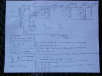
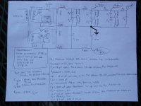
Boywonder, I had a look at your latest PSU schematic, just one thing makes me wonder what is the reason to have Crf in parallel with Lrf, I guess this was the attempt of a "hash filter", if so the capacitor would not be in serial but in parallel with the transformer outlet. Ultimately same inductor can be used in serial with all leads from the transformer/rectifier, though the ground needs only one inductor. Actually I modified your schematic while I was typing, a picture tells more.., have a look, that way the whole right side appears as "black" in regards to RF garbage that might enter from the left side, the mains supply via the mains transformer.
Cheers Michael
Attachments
Last edited:
Ok, the schematic has been corrected for proper voltages, and the CCS was changed to that recomended by the gentleman from across the pond.
An externally hosted image should be here but it was not working when we last tested it.
Eli: Hopefully I have the "hash filter" and the CL150 in the correct loaction.
The CL150 "sits" between the diode cathodes and the PSU filter.
The "hash" filter is in the proper place but it's set up wrong. The "hash" filter is a "routine" LC section made from RF parts. The end of the NPO ceramic cap. shown connected to the 1st filter cap. should be grounded.
You can't bridge rectify the bias tap on Dyna power trafos, as it's connected to the rectifier winding. To use that connection, only a single diode (1/2 wave) is permitted.
Thanks Eli and UT! It looks like Ultima Thule fixed the LC filter. I have zero Dynaco experience but I understand the 1/2 wave bias rectification when a tap is shared. Based on the desire to go back to 460-480V B+ (which makes a lot of sense to me) that last PS schematic is pretty much toast. I'll move the CL 150 in the next attempt.
Several questions about the reduced B+ design.......If the KT88's and the 12AT7 are both getting around 480V B+, is it poor design practice to share the filter tap between them?
Also, what are everyone's thoughts on using a bias tap on the mains transformer vs a separate bias transformer? If there is no need for a start-up delay, then heater and bias voltage can be on the mains transformer without issue.
Last edited:
There is a straight forward KT88 PP stereo version over at DIYTUBE.
diytube.com :: View topic - HK10 - Stereo KT88 / 6550 Push-Pull Amplifier
The power supply looks to be on a wimpy side, though. 😱
Matt:
diytube.com :: View topic - HK10 - Stereo KT88 / 6550 Push-Pull Amplifier
An externally hosted image should be here but it was not working when we last tested it.
The power supply looks to be on a wimpy side, though. 😱
Matt:
There is a straight forward KT88 PP stereo version over at DIYTUBE.
diytube.com :: View topic - HK10 - Stereo KT88 / 6550 Push-Pull Amplifier
An externally hosted image should be here but it was not working when we last tested it.
The power supply looks to be on a wimpy side, though. 😱
Matt:
It's a Mullard circuit, with the (YUCK!) paralleled sections of a 12AU7 as the voltage amplifier. The 6CG7 as the LTP is OK, but where is the overall gain coming from?
You can't bridge rectify the bias tap on Dyna power trafos, as it's connected to the rectifier winding. To use that connection, only a single diode (1/2 wave) is permitted.
Eli: does half wave rectification make for a noisier bias supply vs bridge rectification? Is/was it done to save $$?
Eli: does half wave rectification make for a noisier bias supply vs bridge rectification? Is/was it done to save $$?
Actually, the less (sand) diodes you use the less noisy the PS becomes. 50Hz ripple is not an issue at the currents involved but capacitor quality is painfully obvious in a bias circuit. Use only the best. Diodes too.
There is a straight forward KT88 PP stereo version over at DIYTUBE.
diytube.com :: View topic - HK10 - Stereo KT88 / 6550 Push-Pull Amplifier
An externally hosted image should be here but it was not working when we last tested it.
The power supply looks to be on a wimpy side, though. 😱
Matt:
The PA-060 can handle a KT88 monoblock OK. I'm amazed at the abuse it can take ("two second touch" is that transformers normal operating temp).
It's a Mullard circuit, with the (YUCK!) paralleled sections of a 12AU7 as the voltage amplifier.
Try 1/2 a "DynaMutt" driver 🙂
http://www.diyaudio.com/forums/blogs/geek/140-dynamutt-st-70-should-have-been.html
Cheers!
Actually, the less (sand) diodes you use the less noisy the PS becomes. 50Hz ripple is not an issue at the currents involved but capacitor quality is painfully obvious in a bias circuit. Use only the best. Diodes too.
Only the best in SS diodes means Schottky, which generate "zero" switching noise. FWIW, I have a scheme called "Cockeyed Bridge" used with FWCT rectifier windings that delivers the "noiseless" benefits of Schottky diodes, while holding expense down. 1200 PIV Schottky diodes are costly. If interested, search the archives here and at AA.
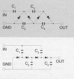
If the OP is going to use DynaClone MK3 power trafos and SS B+ rectification, the "spare" 5 VAC winding can be voltage multiplied to provide both C- for the "finals" and B- for the LTP. Use the 2nd schematic in the uploaded graphic, which was "ripped" from Voltage Multiplier, Inc.
Attachments
FWIW, I have a scheme called "Cockeyed Bridge"
Wow, i have missed this one. Truly worthwhile of a patent. My subjective appraisal of the SIC diodes is not so high but one can surely use a vacuum diode in this arrangement as well.
Only the best in SS diodes means Schottky, which generate "zero" switching noise. FWIW, I have a scheme called "Cockeyed Bridge" used with FWCT rectifier windings that delivers the "noiseless" benefits of Schottky diodes, while holding expense down. 1200 PIV Schottky diodes are costly. If interested, search the archives here and at AA.
If the OP is going to use DynaClone MK3 power trafos and SS B+ rectification, the "spare" 5 VAC winding can be voltage multiplied to provide both C- for the "finals" and B- for the LTP. Use the 2nd schematic in the uploaded graphic, which was "ripped" from Voltage Multiplier, Inc.
Eli, Just to keep the P2P wiring to a minimun, is there any reason not to use this (DIODE SCHOTTKY 1200V 5A TO220-2 - C2D05120A) as a drop in replacement in the first PS schematic? What are the negatives besides cost?
Eli, Just to keep the P2P wiring to a minimun, is there any reason not to use this (DIODE SCHOTTKY 1200V 5A TO220-2 - C2D05120A) as a drop in replacement in the first PS schematic? What are the negatives besides cost?
It appears that they would work fine.....
A related question: Is there no need to bypass these with 10 nf caps since they have no switching noise?
- Home
- Amplifiers
- Tubes / Valves
- Mullard 5-20 KT88 PP blocks!