The last post from Freddie is the right way of doing a balanced in to singelended out.
If you need some examples on doing a feedback network the i would suggest that you go looking on the service manuels for the Aleph amps made by Nelson Pass @ www.passlabs.com
This will give you an idear on how to make a balanced->single ended conversion.
Sonny
If you need some examples on doing a feedback network the i would suggest that you go looking on the service manuels for the Aleph amps made by Nelson Pass @ www.passlabs.com
This will give you an idear on how to make a balanced->single ended conversion.
Sonny
Well... i don't want to convert from balanced to single ended, I want to do the opposite. You see, I designed an amp in this thread, now I've later decided to run it with the capability of balanced input but I still want to employ the original feedback network in the amp if it's needed for good linearity...
EDIT: Well, then, wouldn't my diagram actually work???
Whats wrong with it?
EDIT: Well, then, wouldn't my diagram actually work???
Whats wrong with it?
Since the voltage across the emitter resistors should be in the range of atleast 0,5-1V (R40, and the two resistors in the diff.pair "Q1, Q2"). I have to do some changes.
Here are the calculations I did.
The current flowing through Q3 is:
(2,1-0,65)/560=0,00259A=2,59mA
The current flowing through Q1=Q2 is:
2,59/2=1,295mA
The voltage across R6 is:
0,001295*560=0,7252V
Voltage across R40 is:
0,7252-0,65=0,0752V
Since I want to voltage across R40 to be around 0,5-1V. I have three things that I can change.
1. Increase current through Q1 and Q2 by reducing the value of R7.
2. Increase the value of R6.
3. A combination of the two.
Any suggestions, comments?
Sonny?
Thanks in advance
/Freddie
Attachments
You'd want to increase the current enough to cause the right voltage drop on the resistors, then it'll have the same current flow as originally when the new resistors are there. I hope this explains it enough for you🙂
ehh?
I'm not completly sure what you mean🙂
If I increase the value of R6 to 1k1. I will get 0,75V across Q4.
/Freddie
I'm not completly sure what you mean🙂
If I increase the value of R6 to 1k1. I will get 0,75V across Q4.
/Freddie
also, it would be a good idea to add a current mirror to your long tailed pair, it'll achieve proper balance upon application of power and improve distortion and linearity figures... To see the mirror, just peek at my diagram on this post, you'll see it... It's quite easy to implement and I don't believe it requires any modification of the curcuit mathwise or currentwise...
okay, sorry for my bad description of the current thing...
you must reduce the value of R7 to compensate for the voltage drop accross the 47 ohm resistors
essentially, the current through the curcuit will stay the same, but the voltage drop accross R7 will be less and the voltage accross R6 will stay the same...
say, for example you have 2mA flowing down your LTP, thus R7 drops 1.12 volts and that's that, but say you add the 47 ohm resistors, and you want .5 volts accross them, then R7 must only drop only .62 volts and thus be reduced to 310 ohms respectively to remain at the same current. but this is only an example since .62 volts is much too little accross R7... You'd basically want between 3 and 4 mA flowing down so each side of the LTP gets between 1.5 and 2 mA to idle at and there's enough voltage drop accross R7 to keep the current sink transistor happy at all times... i hope this explains a little better😉
There are some parameters you want to have right first.
To minimize DC-offset you should set the idle current to a optimum level.
So in the VAS stage you want a idlecurrent ~9.5mA. At this current the voltage drop across R9, R10 would be ~51V(R9 and R10 should be .5W resistors).
=> R40 * 9.5mA = ~.95V across R40.
=> .95V+.65V = 1.6V
Idle current in Q1 => 1.6V/R6 => 1.6V/560R = ~2.86mA.
At this point your current through Q3 should be 2*2.86mA => R7 = ~250R.
This is not an optimum value for MPSA06. Use 2N5550/5551 instead.
With MPSA06 the optimum idlecurrent would be around 30mA where the HFE curve is flat.
With 2N5550/5551 2.86mA is perfect. It is faster and the Cob (the capacitance between C-B) is lower than with MPSA06.
Sonny
shoot, I was thinking that you wanted to compensate for addition of tail resistors, i must be tired, but what sonny just described is, of course, correct, so never mind my babble there. But it would still be an interesting idea to add a current mirror...
It's okay to babble!!!
Current mirror is a nice thing to add... Some like it .. some don't .. I do like them.
Sonny
Current mirror is a nice thing to add... Some like it .. some don't .. I do like them.
Sonny
Well, I know it's okay to babble, but I hate it when I get real into detail without first thinking clearly what I was getting into detail about...😀 Anyhow, yes, a current source is a nice addition, but not a requirement, kind of like an opinion basically😉
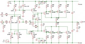
Final version?
Here it is once again.
BTW: Is the value of R11 and R12 critical.
Thanks again Sonny.
Duo, I won't add a current mirror. Lower distorsion does not always mean better sound, and I don't want to make this amp more complicated either. For example I like the sound of my BoZ preamp better, than my OPA604 based preamp. Guess which one has got the lowest distorsion🙂
/Freddie
Attachments
Yeah, like I said, just an opinion, if you're trying to keep it simple, I agree, it's a good way to go about things for sure😀
Also, I believe I read on Rod Elliot's pages that R11 and 12 arent
very critical, but let sonny make a proper point of that cause he probably has more experience with compound pairs😉
And i'd also have to agree that lower distortion doesn't always have to do with better sound. I 've seen some pretty high distortion numbers that meant nothing when you listened to the amp😎
also, thanks to info from sonny, I'll change my input trannies to 2n5550 and 5551, the've got perfect specs
Duo said:also, thanks to info from sonny, I'll change my input trannies to 2n5550 and 5551, the've got perfect specs
uhhmmmm!!! 2N5550/5551 is npn, The complementary pair is 2n5401 - PNP.
First find the datasheet on the fairchild BJT's in the VAS stage. Then i will get back later.
Freddie and Duo : R11 and R12 will form a pole with Cob in the output.
Also : Try figure out wich idle current you will have in the drivers and output in the compound outputstage.
Sonny
okay, well, the current in my OT's is variable, but I'm having trouble with the current mirror... have I got the VAS connected properly?? It doesn't seem like it'll bias properly will it?
The current through the driver pairs in the compound outputstage will not change that much. Only a few mA's.
Replace R21 and R20 with 100R instead of 27R. There can easely be 20mV difference in the VBE of to identical BJT's With 100R a mismatch of 20mV will give a mismatch of 200uA. With 27R this will be 1mA!
KSD401 should at least be HFE class Y not to load your current mirror to hard.
Have you checked the pin combination on the new BJT's?.
Are you sim or building it?
You should have something around 390mV across R20 and R21 @100R.??
Sonny
- Status
- Not open for further replies.
- Home
- Amplifiers
- Solid State
- much less crazy idea