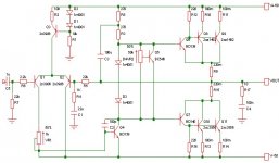
Okay, I took some advice here and there and came up with a design that I think is much more "feasible"... I took a look at esp project 3 http://sound.westhost.com/project03.htm and decided to make my own version with more power output and to be more capable of driving a 4 ohm load. I decided to use complimentary pairs of a1492/c3856 for the OT and BD139/140 for the VAS and drivers, even though I have tip40/41 in my diagram... Does anybody think this is a good idea to make this amp I modified? Please mention if you see something wron in the pic, as in a reversed biased diode,(that sort of thing) Thanks...
P.S. I somehow calculated that this amp sould put out 3000 watts
into a 4 ohm load, which I figure is quite improbable, can I have some pointers for calculating OT power for a class AB please?🙂 😀
P.S. I somehow calculated that this amp sould put out 3000 watts
into a 4 ohm load, which I figure is quite improbable, can I have some pointers for calculating OT power for a class AB please?🙂 😀
Attachments

You are on the right track but you should probably read Mr Elliots articles on how to design amps first.
Some pointers:
You don't need both diodes and Vbe multiplicator. Choose one.
The collector resistors should be one common for both transistors and it should be in the order of 0.1 Ohm. This goes for both npn and pnp side.
You might need to balance your diff amp with resistors. A current mirror is also a good idea.
There should be a DC blocking cap on the input.
Maximum dynamic power into 4 Ohm: Vcc^2/4 minus losses
RMS power into 4 Ohm: Vcc^2/4/2 minus losses
So a value in the right direction is reached with Vcc^2/4/2. This will show a too high figure but it is in the right order of magnitude.
Hope this helps.
/Marcus
Thanks for the pointers, there is a reason I left the double diodes in with the bias servo, if the the wiper on the pot ever opened, the OT transistors would go way way off bias, the idea of leaving the diodes in was to prevent that from ever happening. Next, I did mean to put a cap in the input, just tired from all the reading I've been doing and didn't notice that I forgot it. Next, the collector resistors thing was an accident, I meant to have .5 ohm
common collector resistors, but I accidentally drew two instead, so I just made up their values to "act like" a .5 ohm resistor, but another accident occured when I forgot to put the . in 1.0, ending up with 5 ohms per set of collectors... oops!😱 I will do like you said and put in .22ohm matched resistors, since I have some
nice dual resistor blocks designed specifically for this purpose that came out of an amp with the same transistors... Next, I'm not sure what to do about balancing the diff amp.. Also when you
say vcc^2/4/2 do you mean vcc squared times (2/4/2) or something else?
Read more about the diff amp on ESP and on Douglas Self's site. They explain it better than I do.
The calculation:
Prms = Vcc*Vcc/Z/2, where Z = 4 Ohm in your case.
/Marcus
The calculation:
Prms = Vcc*Vcc/Z/2, where Z = 4 Ohm in your case.
/Marcus
So with your calculation, my amp would put out 1800 wrms (dependant that I could attain full rail to rail swing.) So If I compensate for voltage loss in components, I could get around 1300 watts rms, honestly? I know that the OT devices can take that much current, but it seems kinda fishy... I guess it must be 1300 watts, wow a lot of power!😀
On your drawing (which is rather unclear) it looks like you have +/-60 V rails. This gives:
Prms = 60*60/4/2 = 450 Wrms minus losses in the O/P stage. Perhaps around 400 Wrms in reality.
Since the speaker is connected between the O/P and ground there can only appear one railvoltage over the speaker at a time.
/Marcus
Prms = 60*60/4/2 = 450 Wrms minus losses in the O/P stage. Perhaps around 400 Wrms in reality.
Since the speaker is connected between the O/P and ground there can only appear one railvoltage over the speaker at a time.
/Marcus
Yes, I just figured that out... At first I thought I had the full rail to rail into the speaker, then I though, no wonder it's fishy! So I calculated 450watts for an ideal world and about 400 for a real world... So , I did get on the right track for that one!😀
One last question, do you have any ideas on free software I could download to draw proper diagrams so they are easier to read? I've heard of something called pspice, is it good?
Pspice is a simulation software so if simulating is what you want to do it might be a good choice.
If you want to do PCB layouts then Eagle is a great and cheap choice. You draw your schematic and then you convert to PCB. Can be downloaded from their homepage www.cadsoft.de.
Recomended!
/Marcus
If you want to do PCB layouts then Eagle is a great and cheap choice. You draw your schematic and then you convert to PCB. Can be downloaded from their homepage www.cadsoft.de.
Recomended!
/Marcus
It wouldn't sound very good (if at all) since you have connected the base of the VAS transistor to negative supply.
I still think you should study the diff stage more and make some improvements.
/Marcus
I still think you should study the diff stage more and make some improvements.
/Marcus
Nope. Neither does the BD139/140. At least not if you want to be on the safe side. The O/P devices will manage though.
You need at least a 120 V collector-emitter rating.
/Marcus
You need at least a 120 V collector-emitter rating.
/Marcus
Hmmm, as far as I remember in some esp schematics, the VAS was grounded at the emitter and also, they used a 2n3906 setup on 55 volts, which isn't far off of mine...
EDIT, ooops, I see that my diagram does show a base tied to ground, when I actually intended for it to go to a 1k pot on the long tailed pair.... Darn Gotta fix that quick no wonder the simulator didn't like it!
EDIT, ooops, I see that my diagram does show a base tied to ground, when I actually intended for it to go to a 1k pot on the long tailed pair.... Darn Gotta fix that quick no wonder the simulator didn't like it!
in Rod Elliot's projecto of the 300w sub amp, he has a supply rail to rail of 110 volts and uses bc546 transistors rated at 40vce
Duo
I don't know your source of information, but the datasheets from Philips, Fairchild and ONSemi all quote a Vceo maximum of 80V.
Geoff
I don't know your source of information, but the datasheets from Philips, Fairchild and ONSemi all quote a Vceo maximum of 80V.
Geoff
- Status
- Not open for further replies.
- Home
- Amplifiers
- Solid State
- much less crazy idea