What do you see on the base of Q110?
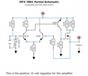
That's the positive regulator. It makes no sense that the voltage is negative.
That's the positive regulator. It makes no sense that the voltage is negative.
You are right. The source I used for a 1D transistor pinout seems to be not right.
MMBTA42 (1D) base is +-31v with a wave on it. Collector has steady -82v rail voltage
MMBTA42 (1D) base is +-31v with a wave on it. Collector has steady -82v rail voltage
There should be only positive voltages on that group of parts. Check the probes where they plug into your meter. The reference (black probe) should be the main ground terminal.
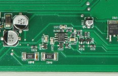
Measure directly across D104 (red probe on striped end). If it measures outside of 15v ±10%, it needs to be replaced.
Measure directly across D104 (red probe on striped end). If it measures outside of 15v ±10%, it needs to be replaced.
D104 measures 15.15V, so within tolerance.
Re-measured Q110, the collector really is -82v. Referenced to main GND
Re-measured Q110, the collector really is -82v. Referenced to main GND
Yes, R145 and R146 are within tolerance.
Also, do you know what value R213 has to be? I can't read the marking on it.
Also, do you know what value R213 has to be? I can't read the marking on it.
With R213, can you re-check? It reads excactly 1000ohm
Voltage over R146 is as good as 0v.
0.005v
Both pads of R146 has minus rail voltage, -82v
Voltage over R146 is as good as 0v.
0.005v
Both pads of R146 has minus rail voltage, -82v
This circuit seems to be correct. I beep every component in the right place.
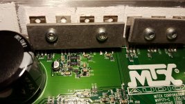
The rectifiers installed next to it are negative rail.
The rectifiers on the other side of the heatsink/ board have positive rail.
Attached is a photo from that side.
The rectifiers installed next to it are negative rail.
The rectifiers on the other side of the heatsink/ board have positive rail.
Attached is a photo from that side.
Attachments
Last edited:
- Home
- General Interest
- Car Audio
- MTX Thunder 81001 component value/schematics