GD folks,
Got A MTX 81000 in, good old school. Both R474, 475 were open. replaced both with new, powered up ok. good rails but no reg LV supplies. Replacing both with 1 ohm 3W through hole parts, the reg LV presented themselves.
Moved onto the class D section, all output FETs (SSP45N20 appear to be original) tested ok.
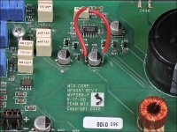
After replacing both optocouplers, the NE5532, and Q239(was shorted), I have 20.33vdc and 19.33vdc across pins 5 and 8 of each optocoupler respectively.
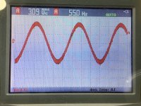
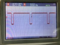
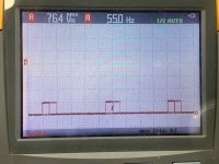
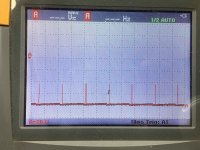
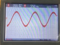
With a 55hz sinewave in, I have audio at pin 1 of the NE5532, and a sqwave at pin 7, at the gates of the output FETs, i only get LS and and very faint HS pulses.
D260, measures 19.52vdc across it.
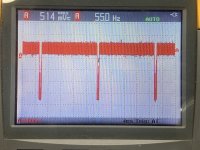
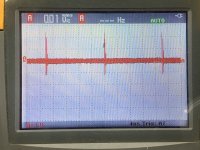
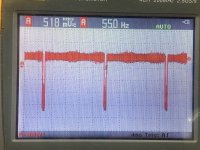
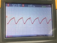
Below are a couple of pics for pins 1 and 7 of the NE5532 and the gate drives at the HS and LS FETs.
Anyone got any pointers on how to proceed?
Got A MTX 81000 in, good old school. Both R474, 475 were open. replaced both with new, powered up ok. good rails but no reg LV supplies. Replacing both with 1 ohm 3W through hole parts, the reg LV presented themselves.
Moved onto the class D section, all output FETs (SSP45N20 appear to be original) tested ok.
After replacing both optocouplers, the NE5532, and Q239(was shorted), I have 20.33vdc and 19.33vdc across pins 5 and 8 of each optocoupler respectively.
With a 55hz sinewave in, I have audio at pin 1 of the NE5532, and a sqwave at pin 7, at the gates of the output FETs, i only get LS and and very faint HS pulses.
D260, measures 19.52vdc across it.
Below are a couple of pics for pins 1 and 7 of the NE5532 and the gate drives at the HS and LS FETs.
Anyone got any pointers on how to proceed?
Attachments
Battery powered scope? If so, unplug it from the mains and post waveforms for pins 2/3 with 3 as the reference and pins 5/6 with 5 as the reference.
Check 2/3 on the other optocoupler. The two optocouplers should see the same signal.
Is LED238 lit?
Is LED238 lit?
No power applied, resistance from leg 3 of the high-side FETs to the positive speaker terminal?
Move the inductors and confirm that the reading doesn't change.
Move the inductors and confirm that the reading doesn't change.
It's OK.
It's a depeltion mode JFET and is 'on' (conducting) when there is no biasing on its gate.
Reinstall it and see if the amp works normally.
It's a depeltion mode JFET and is 'on' (conducting) when there is no biasing on its gate.
Reinstall it and see if the amp works normally.
Arite, just did, while I realised I messed up pulling a data sheet for it.
Replaced it and now I have audio at the speaker terminals.
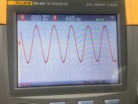
However, I notice around 6v and under, output at the speaker terminals, the wave is heavily distorted, and the final inductors crackle off, if I increase the input signal to where the output goes above 6v, it produces a clean sinewave.
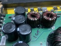
The inductors, don’t get warm with the testing I’ve done so far, and the final caps appear to look as if someone has pressing their tops in.
Replaced it and now I have audio at the speaker terminals.
However, I notice around 6v and under, output at the speaker terminals, the wave is heavily distorted, and the final inductors crackle off, if I increase the input signal to where the output goes above 6v, it produces a clean sinewave.
The inductors, don’t get warm with the testing I’ve done so far, and the final caps appear to look as if someone has pressing their tops in.
Attachments
Is the supply voltage across both optocouplers and the 5532 holding at all output levels?
Did you remove the bridge from the 5532?
Did you remove the bridge from the 5532?
Yup, the supplies across the optocouplers and the NE5532 are holding throughout. yes the jumpers were removed.
Do you have an amplitude of approximately 20v of drive across the gate/source of both the high and low-side FETs when the output is distorted?
- Home
- General Interest
- Car Audio
- MTX 81000D no high side gate drive