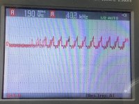
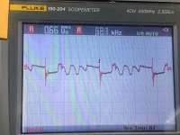
The sine wave at the Spk terminal is lost, I now have this this distortion at varying levels of input signal.
No I don’t have aprrox 20v drive at the gates, ground clip on source, LS (first pic)and HS FETs.
The voltages across the optocouplers and ne5532 are holding constant, except for the HS opto, it drops from 19.33 to 18.15vdc.
No I don’t have aprrox 20v drive at the gates, ground clip on source, LS (first pic)and HS FETs.
The voltages across the optocouplers and ne5532 are holding constant, except for the HS opto, it drops from 19.33 to 18.15vdc.
Attachments
Do you still have a good input to the opto-couplers?
LED still lit?
DCV from gate to source on the JFET?
LED still lit?
DCV from gate to source on the JFET?
Do you still have a good input to the opto-couplers?
it’s the same as in the scope pics earlier
LED still lit?
Yup
DCV from gate to source on the JFET?
0.455v
it’s the same as in the scope pics earlier
LED still lit?
Yup
DCV from gate to source on the JFET?
0.455v
Yup, I pulled j111.
Scope clip on primary ground.
I’m measuring 14.8v on R239, (end that connects to D281) and fluctuating around 6.74v on the other end that connects to gate of Q239. Led 238 lit brightly as the other Leds on the board.
If I lift R239, it restores clean audio at low and high input signal and Led 238 goes very dim.
If you check the JFET gate to source on diode-check (lifted from the board) do you read like a diode one direction and an open circuit in the other direction?
What could have happened to the JFET? Wasn't the amp working normally when you first reinstalled it?
What could have happened to the JFET? Wasn't the amp working normally when you first reinstalled it?
If you check the JFET gate to source on diode-check (lifted from the board) do you read like a diode one direction and an open circuit in the other direction?
Yes, checks out as described.
What could have happened to the JFET? Wasn't the amp working normally when you first reinstalled it?
I don’t believe it’s the jfet, I replaced it with a mmbtj111 with similar results/readings. Now I get clean audio only if I lift R239 (10k, checks ok in and out of circuit).
How long for the LED to light up after remote is applied? All components in circuit as they would normally be.
So, completely off then lit brightly after 4 seconds?
Without the negative voltage on the gate, it will never produce clean audio.
When the LED is lit, what's the DC voltage across the emitter and collector of Q238?
Without the negative voltage on the gate, it will never produce clean audio.
When the LED is lit, what's the DC voltage across the emitter and collector of Q238?
We may need to disable the protection circuit. I need you to confirm that the amp worked perfectly when you had the JFET out of the circuit. Is that accurate?
With the amp operating normally, DCV on all terminals of the LM311 near the shunt resistors, black meter probe on the shunt resistor pad nearest FET246. Don't let your probes slip. These outputs are not available and finding anything that will work may be difficult. Copy and paste the following list and fill in the blanks. If there is no blank space after the colon, add one between the colon and the numbers you enter. It makes it much easier to read.
Pin 1:
Pin 2:
Pin 3:
Pin 4:
Pin 5:
Pin 6:
Pin 7:
Pin 8:
Pin 1:
Pin 2:
Pin 3:
Pin 4:
Pin 5:
Pin 6:
Pin 7:
Pin 8:
No audio, Q240 lifted, LM311 near the shunt resistors, black meter probe on the shunt resistor pad nearest FET246:
Pin 1: 0.0
Pin 2: 0.0
Pin 3: 0.155
Pin 4: 0.00
Pin 5: 9.11
Pin 6: 9.09
Pin 7: 0.236
Pin 8: 9.13
Pin 1: 0.0
Pin 2: 0.0
Pin 3: 0.155
Pin 4: 0.00
Pin 5: 9.11
Pin 6: 9.09
Pin 7: 0.236
Pin 8: 9.13
Those look OK. Confirm that the output of that IC doesn't have anything but 0.24v of DC (with your scope).
If that's what you see, lift Q240, 274 and 280 and check for leakage (meter on ohms/resistance).
What sort of signal do you see on the collector of Q238 with the protection disabled?
If that's what you see, lift Q240, 274 and 280 and check for leakage (meter on ohms/resistance).
What sort of signal do you see on the collector of Q238 with the protection disabled?
- Home
- General Interest
- Car Audio
- MTX 81000D no high side gate drive