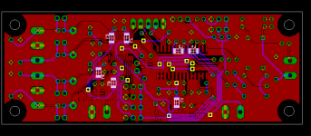
jean-paul said:Are you sure this is still a beta version Russ ? It is looking better by the day. To be honest I did not even see the powerplane, probably because the colors resemble eachother on the picture.
Thanks! I will likely be overcome with happiness if the circuit simply works... 😀
I do want to get it as good as I can though before investing in a batch of PCBs.
So is a the common groundplane taboo? Or is it as good as two joined with a large trace?
Cheers!
Russ
It's all in the document of Guido. Keep the current loops locally and closed. One groundplane should work if decoupling is done well locally. Maybe Guido can shed some light on the pcb. Let's ask him. I mailed him if he can have a look at the board.
It would indeed be nice if the thing actually works the first time.
It would indeed be nice if the thing actually works the first time.
jean-paul said:It's all in the document of Guido. Keep the current loops locally and closed. One groundplane should work if decoupling is done well locally. Maybe Guido can shed some light on the pcb. Let's ask him. I mailed him if he can have a look at the board.
It would indeed be nice if the thing actually works the first time.
Hi,
I just briefly looked at the PCB. It takes quite a while to study such PCB without schematic, though the design looks straightforward.
- I don't see ferrite beads in the supply lines of all digital ICs
- I don't see a direct connect between the 2 grounds of the 8416
- The decoupling seems fairly well placed, close to the ICs
I am happy to see one groundplane, and no powerplane
best
Guido
Thank you very much! You are kind to look it over. I will study your advice and see what I can do.Guido Tent said:
Hi,
I just briefly looked at the PCB. It takes quite a while to study such PCB without schematic, though the design looks straightforward.
- I don't see ferrite beads in the supply lines of all digital ICs
- I don't see a direct connect between the 2 grounds of the 8416
- The decoupling seems fairly well placed, close to the ICs
I am happy to see one groundplane, and no powerplane
best
Guido
Adding ferrites should be no problem.
Guido, if you are agreeable to it I would be very happy to send you the eagle files for even closer inspection.
Cheers!
Russ
Russ White said:
Thank you very much! You are kind to look it over. I will study your advice and see what I can do.
Adding ferrites should be no problem.
Guido, if you are agreeable to it I would be very happy to send you the eagle files for even closer inspection.
Cheers!
Russ
Hello Russ,
Most welcome. Actually we use Protel over here, can't read Eagle files.... PDF is OK though.
cheers
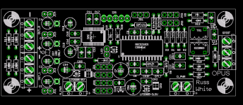
Ferrites added....
And also made a direct GND path between the GND pins on the receiver.
Guido, I will send you a higher resolution image.
Top components are not shown for clarity. The ferrites would be 1206 SMD types mounted on the bottom.
I used a single ferrite for each supply pin.
Cheers!
Russ
And also made a direct GND path between the GND pins on the receiver.
Guido, I will send you a higher resolution image.
Top components are not shown for clarity. The ferrites would be 1206 SMD types mounted on the bottom.
I used a single ferrite for each supply pin.
Cheers!
Russ
Attachments
maxlorenz said:Hi RussHow do you do?
I was thinking...shouldn't I2S DATA also have its 51R termination??
M
Hello Max,
Very well thanks, even if a bit strained in the eyes from re-reading data sheets. 😀
I am looking at page 21 of the WM8740 data sheet, and I do not see the 51R resistor on LRCIN or DIN. So I hope I am OK.

hayenc said:One last question. It would seem we could do differential digital in with some resistor changes. I am not too sure about grounding for differential digital input. Would we only ground at the XLR connector or would we want a third pin on the SPDIF for ground?
Craig has a great question here. It seems easy enough for me just to use a 3 position terminal block instead of two. I will see what I can dig up.
Russ White said:
Hello Max,
Very well thanks, even if a bit strained in the eyes from re-reading data sheets. 😀
I am looking at page 21 of the WM8740 data sheet, and I do not see the 51R resistor on LRCIN or DIN. So I hope I am OK.
They would not hurt at that spot either but I think Max referred to the I2S header...
Russ White said:
Craig has a great question here. It seems easy enough for me just to use a 3 position terminal block instead of two. I will see what I can dig up.
Please keep in mind that the input circuit needs to be adapted as well for 110 Ohm AES/EBU use.
I was looking at the circuit in Appendix A of the 8416 and it looks like it could be worked into the Board without too many kludges.
Switching to Vishay OS_CONS for the power pin caps (70mOhm ESR).
Opinions on using them for the outputs as well?
Opinions on using them for the outputs as well?
It would not be a surprise if the Silmic II sound better at that spot. OSCON is a good choice for decoupling power rails.
- Home
- More Vendors...
- Twisted Pear
- Mr White's "Opus", designing a simple balanced DAC