
Digital and analog supplies are separated on the DAC board and grounds get connected at the DAC board. So 2 of those separated supplies including separate rectifiers + filter caps on one PCB, one circuit for the 3.3V and one circuit for the 5V, would be very nice. Separated supplies have a technical advantage and most toroids/transformers have 2 secondary windings anyway. With 2 secondary windings supplies can be fully separated except for grounds.
Preregulation with a reg certainly is OK but just 2 separated passive supplies on one PCB with or without common mode filters can be a solution too. The main regs are on the DAC board so we can work with unregulated but well-filtered voltages.
With 2 supplies the connectors can be opposite to the power connectors of the DAC board making wiring easier ( with less wire ) and it will be more tidy with both the PCBs mounted in an enclosure.
BTW the DAC board looks cool 😎 I will have to convert balanced outputs to single ended though as all my gear is single ended. Probably I will use Neutrik NTL-1 for converting.
Hi Jean, good input. The idea here is that these PS boards will be used for more than just this project. I have a lot of board that same form factor. The idea is to make these stack.
I like the idea of pre-regulation myself as it allow more flexibility with the transformer. Also it will allow you to play with the exact level of voltage drop across the regs on the DAC.
The PS is meant to be a general purpose regulated PS, but I think it will fit this DAC pretty well as it is the same size.
I didn't want to make something too specific for this DAC, but I guess I could.
When this project is succesful a specific supply PCB will be needed. A very good DAC needs a very good power supply otherwise it won't be a very good DAC 😀
Don't bother too much about the level of voltage drop across the regs on the DAC. A 2 x 6V transformer is about the smallest one can buy and the regs won't choke on 8 to 9V Vin although a lower voltage would be nicer. Dissipation is low as the chips do not consume much power. I would dare to use a 2 x 4.5V toroid if they still existed with the ultra lowdrop regs as used on the DAC PCB.
The Crystal consumes about 33 mA at 192 kHz. The LP reg will dissipate about 150 mW at that frequency with a 6V transformer.
The Wolfson consumes about 32 mA in total when fed with 5V. Dissipation of its reg will be around 100 mW.
I excluded the LED in the calculation.A low current type will glow with 1 mA.
jean-paul said:When this project is succesful a specific supply PCB will be needed. A very good DAC needs a very good power supply otherwise it won't be a very good DAC 😀
I was hoping the PS I designed here was both "good" and flexible. 🙁
What would be required to make it "very good"?
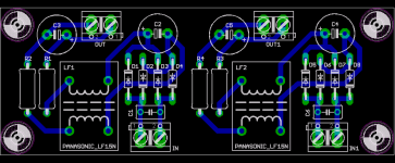
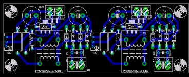
I don't mind doing a layout for two unregulated power supplies on a single PCB. With terminal blocks that correspond with the DAC terminal blocks.
I am unfamiliar with common mode coils, but I will look into that.
Cheers!
Russ
It is good and flexible but 2 will be needed which makes it less flexible IMO ( more drilling, more wiring ). Please see post 183. I guess making it good in my opinion implies 2 separate supplies on one PCB each with their own Schottky rectifiers decoupled with a 1000 or 2200 uF 16/25V low ESR electrolytics paralleled with (a) quality film cap(s) and with common mode coil followed by a 1000 or 2200 uF 16/25V low ESR electrolytics paralleled with a quality film cap. Instead of the coil a discrete/IC preregulator can be used with a small cap at its output, a matter of taste as there are regs on the DAC board. A power LED + resistor could be incorporated in the design.
This is an opinion though and nothing more, the choice is yours. The final result will depend on the quality of the supplies which is why they deserve attention. The term "very good" is quite subjective and it depends who you ask what the answer will be. Some will recommend discrete regs like Jung regs, cap multipliers ( also very good ! ), shunt preregs etc.
http://www.hoer-wege.de/da_power.htm
Common mode coils:
http://industrial.panasonic.com/www-ctlg/ctlg/qAEL0000_WW.html
I'm not exceptionally fussed about a PSU board at the moment. I have lots of bits and pieces and several existing layouts that could be modded. Oh, and I'm sure I read somewhere that the Jung regs weren't particularly stable at low voltages like 3.3V and 5V?
ALW regs?
Pinkster,
Do the ALW reg's (modelled after Jung's et al) fall into the "not particularly stable" category?
Pinkster,
Do the ALW reg's (modelled after Jung's et al) fall into the "not particularly stable" category?
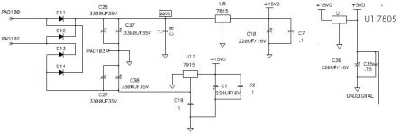
OK Guys, I am cooking up a conventional (C-L-R-C filtered) unregulated dual supply PCB, but if any of you spot anything wrong (or something which could be easily made better) on the DAC PCB please by all means fuss! 😀
Re: ALW regs?
I don't know. It was something I remember reading online somewhere, and for the life of me, I can't find it now. If anyone else has more info please yell out, even if I'm completely wrong.
Ed Lafontaine said:Do the ALW reg's (modelled after Jung's et al) fall into the "not particularly stable" category?
I don't know. It was something I remember reading online somewhere, and for the life of me, I can't find it now. If anyone else has more info please yell out, even if I'm completely wrong.
Hi Ed,
OT:
They should be stable on 5V...
Ask Andy 😀 ...or goto:
http://www.pinkfishmedia.net/forum/forumdisplay.php?f=8
Plenty of info and tweaks to ALWSR's.
Cheers,
M
OT:
Do the ALW reg's (modelled after Jung's et al) fall into the "not particularly stable" category?
They should be stable on 5V...
Ask Andy 😀 ...or goto:
http://www.pinkfishmedia.net/forum/forumdisplay.php?f=8
Plenty of info and tweaks to ALWSR's.
Cheers,
M
Russ White said:OK Guys, I am cooking up a conventional (C-L-R-C filtered) unregulated dual supply PCB, but if any of you spot anything wrong (or something which could be easily made better) on the DAC PCB please by all means fuss! 😀
I thought DAC's need a regulated supply.
-David
dw8083 said:
I thought DAC's need a regulated supply.
-David
The regulators are on the DAC PCB. It is locally regulated.
- Home
- More Vendors...
- Twisted Pear
- Mr White's "Opus", designing a simple balanced DAC