From the video I referred to, it was evident that the test figures were recorded in short form on the adhesive tape that the operator used to hold pairs together. This looked like a significant mismatch but you could not say from the brief glimpse in the video, just how much was acceptable or which of the pair had the higher or lower measurement. So again yes, the LTP were not matched pairs.
I can say that the LTP transistors I recall replacing, were given to me as a mismatched pair, labelled individually as TR1, TR2 but I never learned at the time, who performed the testing or the significance. As DaveS mentions, the large TR1 collector resistor means a lower DC voltage across TR1 but the current in either transistor is still more or less balanced by the operation of the LTP circuit. The question is; what difference does this deliberate flaw (it was actually a common design feature at the time - ref. Douglas Self) make to the sound quality and why do it?
According to a personal interview, Vereker was trying to operate his amplifiers with the lowest possible bias currents at the output and input stages and he was successful though this meant his general design was unusual in a market flooded with imports that used conventional, somewhat excessive bias or even class A as a cure-all for crossover distortion and related ills. Looking at more recent products, I think most of Vereker's ideas have now been abandoned by Naim and it's back to textbook, low THD engineering philosphy. Perhaps someone with a critical understanding of the NAP design evolution would like to comment on that suggestion.
Last edited:
I can't talk about the difference in "sound" but on the other hand with TR1 and TR2 shifted I have almost no offset at the output and a perfectly silent power-up.
Exactly like it should  ! Remind me Huggy, is your amp a clone or an original model? We have discussed the LTP transistors here at the NAP140/ Ebay thread, long ago but I don't recall whether you had built a clone or were repairing a Naim product then.
! Remind me Huggy, is your amp a clone or an original model? We have discussed the LTP transistors here at the NAP140/ Ebay thread, long ago but I don't recall whether you had built a clone or were repairing a Naim product then.Correct at now time Steve Sels changed schematic to self design and if you have touch to truth Naim sound you need buy old chrome amps and preamps.I think most of Vereker's ideas have now been abandoned by Naim and it's back to textbook, low THD engineering philosphy. Perhaps someone with a critical understanding of the NAP design evolution would like to comment on that suggestion.
I think Steve S make as Steve Audio amps and the new device of Naim Audio is not have Naim Sound 🙂)
In attachment Steve and Steve design
Attachments

Last edited:
It was mentioned a couple of times on the forum and also on PFM how they "matched" the BC239s: in an amp board with one BC239 permanently fitted they would test the batch in the other place: the ones which give identical DC offset were considered to be matched. Later they replaced it with a dedicated test device...
nap90 clone as close as possible off the original modelI can't talk about the difference in "sound" but on the other hand with TR1 and TR2 shifted I have almost no offset at the output and a perfectly silent power-up.

The question is; what difference does this deliberate flaw (it was actually a common design feature at the time - ref. Douglas Self) make to the sound quality and why do it?
Have you tried it?
It makes a surprising difference to the sound. With 22K fitted the sound is full and warm and "Naimish", with 1k fitted the sound is more like a conventional amp - clearer and brighter.
I always meant to measure the distortion profiles for each option, but never got round to in and no longer have any Naim(like) boards to play with. (Actually I do have NCC300s but my configuration for these makes component changes a PITA).
I did find that 22K made the loop minutely less well compensated. It didn't affect o/p offset in any meaningful way.
Yes, many times as part of tinkering about, bridging or shunting resistors and so on to familiarise myself with what makes the amplifier "tick", whenever I drag it out for some experimentation. 'Funny that I never hear the music the same way each time. It's always a bit different and elusive but I guess I'd need to be a "golden ears" audiophile for that.
Strange coincidence. I have been hunting for the details of NAP90 for several hours now, because it still has such a good rap. and is quite expensive for a basic, old 30W amp. Thanks, for the advice. Do you have any schematic(s) or references to them, maybe a PCB you used, which would near enough detail what you built?nap90 clone as close as possible off the original model
That just doesn't seem an appropriate method for sorting and matching pairs as it only compares all transistors to one particular example. The yield of differential matches would probably be very low because of the statistical spread of hFE within the nominated C grade. An alternative would be to repeat the matching process with other acceptable gain values that were likely to suit but this becomes expensive and still leaves you with useable product that meets the supplier's specs but doesn't get accepted. I think there would be more to the matching jig than the explanation suggests, otherwise it would be rejected too.It was mentioned a couple of times on the forum and also on PFM how they "matched" the BC239s: in an amp board with one BC239 permanently fitted they would test the batch in the other place: the ones which give identical DC offset were considered to be matched. Later they replaced it with a dedicated test device...
As I recall, there was a long running dispute over the supply and rejection of these semis because no manufacturer could sensibly agree to Naim's extreme conditions of acceptance without performing 100% sorting and matching themselves.
Last edited:
in fact, to be exact, I cloned the power part of a naim NAIT3 first series that I had at the time at the workshop and which is the same as the NAP90.
As I recall, there was a long running dispute over the supply and rejection of these semis because no manufacturer could sensibly agree to Naim's extreme conditions of acceptance without performing 100% sorting and matching themselves.
As far as I'm aware Naim bought from Semelab, a disti, who did all the selection for them... at a cost. I expect other companies got all the rejects.
Semelab had a very nice niche supplying pretty much all of the UK audio industry.
I understand that's correct regarding Sememab's involvement (and cosy arrangements with Profusion and Farnell too). Of course, they are still involved with the supply of Naim's house branded power transistors. Their high-rel and otherwise expensive products seem to have long been an integral part of Naim's quality and reliability scheme.
The drivers and small signal types were Ferranti/Zetex or Motorola, back in the 1970's-90s. The SMD versions now used are still largely original types, probably manufactured somewhere in SE Asia but I doubt that any pair matching would be performed there.
The drivers and small signal types were Ferranti/Zetex or Motorola, back in the 1970's-90s. The SMD versions now used are still largely original types, probably manufactured somewhere in SE Asia but I doubt that any pair matching would be performed there.
In this forum someone measured orjinal Naim's Hfe of BC239c's. They were nearly equal Hfe's. I don't know but I'm assuming Naim's offset nearly zero(isn't it)?
I used same Hfe BC239c's and my offset was 10+ mv. Then, I tried %10 less Hfe for tr2(nearly hfe tr1, 600 & tr2, 550). Now, my offset has changed to 2-3mv. I were used 100ohm emitor resistors. This is not from original diagram. Is this difference from that 100ohm's? If not I'm confused all..
I used same Hfe BC239c's and my offset was 10+ mv. Then, I tried %10 less Hfe for tr2(nearly hfe tr1, 600 & tr2, 550). Now, my offset has changed to 2-3mv. I were used 100ohm emitor resistors. This is not from original diagram. Is this difference from that 100ohm's? If not I'm confused all..
It has very little to do with the 100R resistors.
O/p offset is affected by:
- Effect of base current of TR 1 and 2 through 2K7 + 24K input resistors and 27K feedback resistors respectively
- Base current depends on hFE of TR1 and 2 - which varies with temperature
I am surprised that target Tr1 gain is higher than Tr2 (on a bench test) because Tr2 has lower temp and lower Vce which believe should result in lower gain. However it's a complex situation and I musst have misunderstood or overlooked something.
In the end, a bit of offset doesn't really matter, unless you are connecting headphones directly to the output.
O/p offset is affected by:
- Effect of base current of TR 1 and 2 through 2K7 + 24K input resistors and 27K feedback resistors respectively
- Base current depends on hFE of TR1 and 2 - which varies with temperature
- Vbe of Tr1 and 2 - which is affected by their temperatures. TR2 will run a bit cooler due to the lower VCE compared to Tr1
- Balance of TR1 and 2, which is affected by the hFE and Vbe of the VAS transistor
I am surprised that target Tr1 gain is higher than Tr2 (on a bench test) because Tr2 has lower temp and lower Vce which believe should result in lower gain. However it's a complex situation and I musst have misunderstood or overlooked something.
In the end, a bit of offset doesn't really matter, unless you are connecting headphones directly to the output.
here is a schematic of a naim nap90 from somewhere in the forum,Strange coincidence. I have been hunting for the details of NAP90 for several hours now, because it still has such a good rap. and is quite expensive for a basic, old 30W amp. Thanks, for the advice. Do you have any schematic(s) or references to them, maybe a PCB you used, which would near enough detail what you built?
but i dont know if it is real..........
Attachments
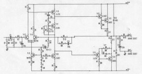
Thanks for finding and posting that schematic, mjf. It does look like it was drafted correctly from an original NAP90 product, minus the SOA protection, as said. One detail that isn't clear in the image, is the power supply voltages which could be 25 or 29VDC by my reading. I'll guess at +/- 29V and that suggests a 22+22VAC toroid of 160-250VA. Too bad that a stock 22V option was eliminated a few years ago. Hmm!
Good day power in Nait transformer ~17-0-17Thanks for finding and posting that schematic, mjf. It does look like it was drafted correctly from an original NAP90 product, minus the SOA protection, as said. One detail that isn't clear in the image, is the power supply voltages which could be 25 or 29VDC by my reading. I'll guess at +/- 29V and that suggests a 22+22VAC toroid of 160-250VA. Too bad that a stock 22V option was eliminated a few years ago. Hmm!
And power on power caps +-24-0-24
Also when I make my amp by nait design I use 18-0-18 transformer
Somebody of my friends tell me about low power out from Nait design. But when I listen my amp by nait design power very well for small room and middle acoustics
Last edited:
- Home
- Amplifiers
- Solid State
- MPSA18 VS BC239C