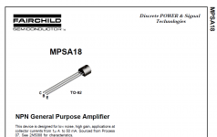
Btw, and as apparently noone noticed it yet: BC550C also is EBC.The screen printing on the pcb is done for the MPSA18 that have EBC pinout instead the BC550C have BCE pinout
Best regards!
No, I don't. In the 1970ies most European SS plants and manufacturers replaced their previous small signal transistors of wide spread designation numbering by the BC54x, BC55x line (plus BC560, of course). Hence, BC239C is obsolete for decades now. It's direct replacement is BC549C.
Best regards!
Best regards!

Dear mdardenis BC239c is natural sound in naim nap amplifiersDo you think BC239c better than BC550c? In datasheet BC550 looks like better?
If you use bc550 or bc547 sound is very hi midrange and not natural I testing this 🙂) I have all bc550/546/547 and all 2n50xx and 2n59xx and I tested all with nap amp
BC239c is excellent for Naim nap
Also if you have 2sc2240 this device very cold for sound in nap amps
bc547/557 excellent works only in Naim DR regulators in HICAP DR version only
Attachments
Last edited:
The difference, or if you prefer to say "natural Naim sound" is in the production hFE spread and match of the semis, not so much the BC type. BC239C were known to have a wide hFE range, up to 500 typically, with even a few at 1200 hFE but you wont find that with later BC549 product, depending on the particular manufacturer and their quality control regime, and there were several competitors in Europe, UK and US.
Don't forget the intentional hFE mismatching that Naim used for their LTP transistors. It required a high average hFE level to begin with and was the reason for a high number of incoming batches being rejected by Naim then disputed by the supplier(s). Incidentally, if you follow the old articles and videos that showed and discussed features of their assembly line, you'll see that's how Naim nulled the DC offset (and quite predictably) by selection on test of a suitable ratio between each transistor in a particular LTP. No cr*ppy trimpots there but not much fretting over having the lowest possible THD either !
!
Don't forget the intentional hFE mismatching that Naim used for their LTP transistors. It required a high average hFE level to begin with and was the reason for a high number of incoming batches being rejected by Naim then disputed by the supplier(s). Incidentally, if you follow the old articles and videos that showed and discussed features of their assembly line, you'll see that's how Naim nulled the DC offset (and quite predictably) by selection on test of a suitable ratio between each transistor in a particular LTP. No cr*ppy trimpots there but not much fretting over having the lowest possible THD either
!
Last edited:
Thank you for answers! I have also BC239C. but, I don't know it's orginal or not. I tested before, I prefered BC550. BUT, I only tested with one channel 🙂 this is a mistake..
As said, the question of what specific LTP transistor type doesn't really matter. What does matter is that they are similar in all but actual measured hFE and:
1. Genuine low noise, high gain, small signal amplifier type.
2. High, as in >350 hFE (or beta) and a suitable mismatch of it in each LTP pair to achieve a low DC offset. Unfortunately, if you only have a few transistors to test and select from, this is not really possible.
https://www.farnell.com/datasheets/105081.pdf
As a warning, some years ago I bought 250 of these BC239Cs from a European Ebay seller but soon realised from testing, that they had already been picked over for (likely) the same purpose. There was almost nothing I could use from those 250 semis and it's amazing how deceptive some private Ebay rip-off merchants can be! So, I learned the hard way that if there is a choice, always buy through-hole style semis in untouched, tape & reel format (yes, even though I received some taped semis that had been tampered with too ).
).
1. Genuine low noise, high gain, small signal amplifier type.
2. High, as in >350 hFE (or beta) and a suitable mismatch of it in each LTP pair to achieve a low DC offset. Unfortunately, if you only have a few transistors to test and select from, this is not really possible.
https://www.farnell.com/datasheets/105081.pdf
As a warning, some years ago I bought 250 of these BC239Cs from a European Ebay seller but soon realised from testing, that they had already been picked over for (likely) the same purpose. There was almost nothing I could use from those 250 semis and it's amazing how deceptive some private Ebay rip-off merchants can be! So, I learned the hard way that if there is a choice, always buy through-hole style semis in untouched, tape & reel format (yes, even though I received some taped semis that had been tampered with too
).A few points IME:
- All the BC239Cs I tested had a breakdown voltage >60V, so OK to use in the LTP.
- Gain matched pair for LTP gives very low o/p offset voltage. I believe the mismatch in beta came from a desire to have a small positive o/p offset.
- Both halves of the LTP run at approximately the same current (VAS base current has a small effect on the balance). They have different collector voltages though, due to the 22K resistor's voltage drop.
- A significant proportion of the "Naim sound" comes from the power supply, which nobody seems to pay much attention to.
Also, I used 2.5mm diameter 3-4meter length copper speaker cable, it change the sound which I don't expect.
"A significant proportion of the "Naim sound" comes from the power supply, which nobody seems to pay much attention to." I red this in this forum. We need special transformer.
"A significant proportion of the "Naim sound" comes from the power supply, which nobody seems to pay much attention to." I red this in this forum. We need special transformer.
The mismatched pairing of LTP transistors prior to assembly, was a documented, specific task reserved for one of Naim's expert assembly staff, who proudly showed her collection of tested, taped together pairs of TO92 transistors in a video, as evidence. This was a highlight of one of Naim's early videos that seems to have disappeared recently from YouTube but it has been discussed in the past here and also at PFM forum. This pre-matching was a definite part of the quirky Naim design and manufacturing process for all the NAP and Nait series models up to at least the olive green series, AFAIK.
I've built and 'trouble shot' enough clones to see that's the only simple way you could do this in a manufacturing environment. Otherwise, it would have to be nulled by adjusting a conventional trimpot for the LTP current balance, after a suitable warm-up time. Note that even with it's closed box, the warm-up time for a typical Naim amp is a very long 20-30 mins before the internal temp. is stable at idle. A DIY version may be quite different to a closed, 2.5-4mm thick sheet or extruded aluminium box though.
Regarding special power transformers, I'm not sure what is meant by special. A toroidal transformer is usually specified for all high quality power amplifiers and these generally have a singular type of construction with only the steel grade, appropriate overall dimensions and wire size to select for the power rating. E-I laminated transformers have much higher resistance and probably will perform differently at high power levels.
Special transformer; there are 4 output not 3.Regarding special power transformers, I'm not sure what is meant by special. A toroidal transformer is usually specified for all high quality power amplifiers and these generally have a singular type of construction with only the steel grade, appropriate overall dimensions and wire size to select for the power rating. E-I laminated transformers have much higher resistance and probably will perform differently at high power levels.
Ah, I guess you mean that the output winding is centre-tapped rather than 2 separate windings.
No problem - Toroidal transformers are almost always wound with pairs of windings because that allows easier bifilar style and balanced (i.e. 2 wires wound together) construction, which is easier and more efficient while offering more flexibility of application. Conventional E-I laminated transformers are usually a single winding that is tapped (twisted into a small loop) by the operator at roughly half the number of turns for a centre-tap , but only if required for say, a dual rail power supply.
A toroidal transformer has the end wires of both windings brought out separately so you then join the correct ends in series, according to the wire colour coding provided by the manufacturer or if that isn't available, you can experiment with safe, low AC voltage to see which arrangement cancels or doubles the output voltage measured over both output windings. Either E-I or toroidal, you will still have effectively 3 output wires to make the usual dual rail power supply.
https://talema.com/introduction-to-toroidal-transformers/
Last edited:
I understand you. But, I have 2 more toroidal transformer have only 3 output wires. And I couldn't test that diagram:A toroidal transformer has the end wires of both windings brought out separately so you then join the correct ends in series, according to the wire colour coding provided by the manufacturer or if that isn't available, you can experiment with safe, low AC voltage to see which arrangement cancels or doubles the output voltage measured over both output windings. Either E-I or toroidal, you will still have effectively 3 output wires to make the usual dual rail power supply.
https://talema.com/introduction-to-toroidal-transformers/
.jpg") What do you think about this psu?
What do you think about this psu?I won't comment on the PSU design above other than to say that AC common from the transformer is normally grounded to the same node as DC common of the output. Look for simple, conventional designs that have similar load capability and applications to your amplifier.
The argument for having dual rectifier bridges (one for each rail) only works properly for balanced loads but a stereo audio output can't or should not be considered as balanced. https://theorycircuit.com/35-volt-dual-power-supply/
https://www.eevblog.com/forum/projects/dual-bridge-rectifier-why/
You'll find enough info. there for suggestions as to what would best suit your amp and budget.
The mismatched pairing of LTP transistors prior to assembly, was a documented, specific task reserved for one of Naim's expert assembly staff, who proudly showed her collection of tested, taped together pairs of TO92 transistors in a video, as evidence. This was a highlight of one of Naim's early videos that seems to have disappeared recently from YouTube but it has been discussed in the past here and also at PFM forum. This pre-matching was a definite part of the quirky Naim design and manufacturing process for all the NAP and Nait series models up to at least the olive green series, AFAIK.
I've built and 'trouble shot' enough clones to see that's the only simple way you could do this in a manufacturing environment. Otherwise, it would have to be nulled by adjusting a conventional trimpot for the LTP current balance, after a suitable warm-up time. Note that even with it's closed box, the warm-up time for a typical Naim amp is a very long 20-30 mins before the internal temp. is stable at idle. A DIY version may be quite different to a closed, 2.5-4mm thick sheet or extruded aluminium box though.
Regarding special power transformers, I'm not sure what is meant by special. A toroidal transformer is usually specified for all high quality power amplifiers and these generally have a singular type of construction with only the steel grade, appropriate overall dimensions and wire size to select for the power rating. E-I laminated transformers have much higher resistance and probably will perform differently at high power levels.
Interesting. There are reports of PFM of people who have pulled LTP devices from old Naims and measured the gain... they were all over the place.
I never found warmup to affect the dc offset significantly. Both LTP transistors warm up together (albeit one is slightly cooler due to the 10V or so lower collector voltage resulting from the 22K resistor).
The thermal feedback loop for bias current is a different matter. It's all a bit of a fudge!
Naim reckons that transformer need to be "low impedance" to provide a short conduction angle. Make of that what you will.
There are lots of tales of humming transformers with Naim kit, which seems to support the low impedance/fewest turns possible theory (= high flux density and operation near core sauturation).
- I changed the BC550c's with BC239c's. BC239's Hfe's complately similar (590/591 & 614/614). BC550's Hfe's had very nearly. So, dc offset didn't change with BC239's.
- Bias continuously changing with temprature of case. It's not stable. case box almost close, not air flow in it. Then, bias increasing with temp. of case.
In my experience, Naim's product design and quality story is rather chequered, largely due (just my opinion) to its beginnings with an amateur, albeit a very talented and enthusiastic one, at the helm. This resulted in a lot of unconventional and perverse ways of achieving some unusual design aims that actually appealed to a lot of audio enthusiasts who sought better, more musical and engaging sound from local British products, back in the day. You only have to look at the original products in the first series up to the "Chrome Bumper" era to see that Naim's gear was not typical of the period in any aspect of appearance or performance.
The first model I encountered was a recap job of NAP 120 for the local sales and service agent who was busy with some other work at the time. Oh boy, what a weird construction! Heatsinks fabricated from standard window extrusions, ill-fitting clamps for the caps, odd mix of small signal transistors and the finish was more matt than satin black paint over poorly etch-primed aluminium. Echh! The agent only listened and grinned when I stated my critcisms and handed the beast over for his imprimatur. Wisely, he wasn't going to be drawn into a slanging match over one of his product lines.
The LTP transistor "match" would have been a more or less constant ratio of hFE within a workable range of values rather than simply a narrow range of values, otherwise the volume of rejects would surely and statistically have been many times the number of acceptable parts. I'd say that gives credence to the finding that LTP transistor hFE or gain was all over the place. It was almost as different with 2 NAP140s and Nait I have owned too, though I had no reason to change them for anything else and they seemed to sound just as good as later versions.
If anyone still recognizes JV's PRAT nemonic, this particular sound effect is also influenced by the LTP balance and if you balance it conventionally, there's some loss of another of Naim's endearing little squeaks and shrieks. When you're done with re-establishing conventional design features though, a Naim sounds pretty bad so you really need to keep it original if possible, to sound best .
Last edited:
Do you say LTP Hfe must be unbalanced (perhaps it's written as %10 difference)? Or about LTP's collector resistors?If anyone still recognizes JV's PRAT nemonic, this particular sound effect is also influenced by the LTP balance and if you balance it conventionally, there's some loss of another of Naim's endearing little squeaks and shrieks. When you're done with re-establishing conventional design features though, a Naim sounds pretty bad so you really need to keep it original if possible, to sound best .
- Home
- Amplifiers
- Solid State
- MPSA18 VS BC239C