Thanks to keantoken for pointing me to this thread.
There is a notch filter in the setup I used to create that FFT, which attenuates the fundamental by 30dB, so the harmonics should be read directly from the scale, not compared to the fundamental....If you look at the fft that is on the Mr.Evil site, you will see that 2º is at -70db of the fundamental , its not 0.00075 % for sure...
I just figured out how to subtract magnitude in Baudline and got the THD figure of -112db. That's .00025%. Not bad?
The version I got these results with is basically the last schematic with BC337-40 NPN's and R1/R2 bypasses since they come out to only 4R or so.
The version I got these results with is basically the last schematic with BC337-40 NPN's and R1/R2 bypasses since they come out to only 4R or so.
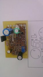
Have already finished the HECshunt PCB , and done some preliminar test´s.
The power supply is stable, no signs of oscillation.
Very low noise floor. And very hight PSRR.
The output impedance is 30uR at 150 Hz, 60uR at 1Khz and 600uR at 18Khz.
I think the impedance increase at higher frequencies is caused mainly by the skin effect of the cooper wire, that connects to the load. I will have to use a better setup in the next test´s that I will do (perhaps use litz wire). nonetheless I am very pleased with the results .
It measure 75mm by 50mm
😎
Attachments
Kean, so R1,R2 are not necessary any more ?
Maybe, if you use BC337-40 and yours happen to have the same Vbe as mine. They should have roughly 60mV +-5mV more Vbe than the BC550C. If it's less than that, the world won't end, but you'll get more than 20mV offset.
So BC560C in the input stage and BC337-40 in the output stage ?
Sorry about this stupid questions but i print out the schematic to build and then it is good when i do not have to think much.
Sorry about this stupid questions but i print out the schematic to build and then it is good when i do not have to think much.
For use as the output buffer based on these schematics, yes:
http://www.diyaudio.com/forums/analogue-source/218625-paradise-builders.html#post3189527
Turn-on behavior should be verified to be benign.
http://www.diyaudio.com/forums/analogue-source/218625-paradise-builders.html#post3189527
Turn-on behavior should be verified to be benign.
As I expected, Elvee has done similar things and provided me with some links:
http://www.diyaudio.com/forums/solid-state/184895-halve-diamond-double-performance.html
http://www.diyaudio.com/forums/solid-state/185501-unigabuf-follower-cut-out-leader.html
http://www.diyaudio.com/forums/solid-state/218019-distortion-cancelling-buffer.html
I haven't seen anyone else with my specific implementation, but there are many different versions and most of them perform excellently.
The philosophy with my version was to get the best inherent null possible. In effect, using equivalent devices to cancel so that the 3rd and higher harmonics would cancel just as well as the 2nd. Theoretically, this should be the most benign for audio assuming all other critical factors were taken care of.
Kean, one thing that I remember today, was using your circuit in an output stage of a power amplifier, do you think it will perform ok in a class B stage ?
If it's used in place of the drivers it will work. If you try and make it class B you may succeed in getting a strange transfer curve, but not total distortion cancellation.
Oh, and I want to point out that I got .0003% THD and none of the transistors were actually thermally coupled! So this circuit seems to be more tolerant than even I thought originally.
Can this (http://www.diyaudio.com/forums/analogue-source/154210-mpp-927.html#post3554680) be built using a non simetric psu ex: +20V - 0V ?
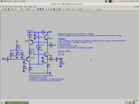
The voltage at the circuit's "ground" needs to be halfway between the rails. Something like this.
EDIT: Better schematic.
EDIT: Better schematic.
Attachments
Last edited:
Oh, and I want to point out that I got .0003% THD and none of the transistors were actually thermally coupled! So this circuit seems to be more tolerant than even I thought originally.
What was the load and the voltage ?