I want to openly thank Frans for all the night work and inconditional support 🙂
Thanks Ricardo, It was a pleasure to do this together with you 🙂
Where does this scheme come from?
Thanks.
It´s from an austrian electronics magazine called "ITM Praktiker" in the
early eighties. It was used in a project called "modular preamp".
Paul Skritek ( Handbuch der Audio - Schaltungstechnik: Amazon.de: Paul Skritek: Bücher ) designed it, I believe.
Paradise documentation
Hi Joachim or anyone else,
since group buy is already over and I am coming late -as always- I might think of designing the PCB for the Paradise phono stage and PSU myself. Can anyone please post the most recent documentation, schematics, BOM and PCB layouts?
I was trying Holgers Paradise-forum but for some reason the page about the documentation did not open.
Thanks a lot!
Look here for starters: http://www.diyaudio.com/forums/analogue-source/218625-paradise-builders-2.html#post3189527
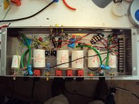
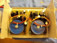
The second channel of the tube phono for ETF is working !
I only have to do some mechanical work ( put the PSU in a box ) and then i can test it in my system.
The square with Anti RIAA look decent. I have a slight subsonic filter under 30Hz so the top is not totally flat.
I only have to do some mechanical work ( put the PSU in a box ) and then i can test it in my system.
The square with Anti RIAA look decent. I have a slight subsonic filter under 30Hz so the top is not totally flat.
Attachments
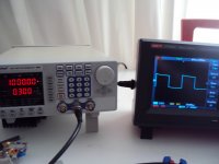
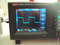
Is the Peak Tech generator totally flat top on its own when the scope is DC coupled for under 100Hz signals? So the slope we see is totally the phono subsonic's own?
I think so. With the same generator and my solid state stages i get a flat top.
I will check that again.
I will check that again.
They normally are flat, some high MHz DDS ones may just show jitter in audio frequencies. But its good to check. Looped with a BNC cable to scope should suffice. 50 Ohm terminated even better.
Grounding
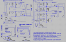
A few weeks ago Rcruz asked some questions about having one transformer for both power supplies of the Paradise, his main concern was ground loops and ground induce noise. For this reason I tried to create a grounding scheme that both is simple and ‘fool’-proof.
Attached is the schema that I came up with (after numerous discussions with RCruz), there is one ‘new’ idea in the schema and that is to introduce one ‘extra’ wire in the connection between the record player and the preamplifier. Conventionally a record player is connected to the preamplifier by 5 wires +L, -L, +R, -R and ground, this scheme uses 6 wires (more must be better 🙂).
As I see it, the problem is the ground wire (in the 5 wire ‘standard’ scheme), there are 3 possibilities, the ground wire is connected to the tone arm, it is connected to the chassis or it is connected to both. In my opinion all three solutions are bad. The first leaves the chassis floating, the second leaves the tone arm floating and the third connects the chassis to the tone arm (and that includes all HF and ground induced noise that is picked up by the environment, mains cable, mains ground etc.).
The best solution seems to be to connect the chassis of both devices, the player and the preamp, to each other, but this will create ground loops via the mains ground and audio signal cabling (so it needs to be un-looped). Also the tone-arm should be connected to the ‘clean’ ground of the preamp. The schema, as attached, removes every possible ground (clean or mains) loop and at the same time removes all touch induced noises.
The schema for single transformer has been build and tested by RCruz and works as expected (total silence 🙂 no hum’s). The schema for two transformers (is preferable) is even better, it makes sure that the only place where both channels are connected (zero ohm) is in the line amplifier.
Let me know what you think of it, do not hesitate to ask questions, and please report your experience if you did implement the schema.
Attachments
Last edited:
A miracle happened, it works ! With a Siemens E188CC gold pin in the output i ran into wild oscillation, with a JJ E88CC it works just fine, strange.
Noise is not as low as my solid state designs but listening with MC ( Lyra Titan i ) is possible. Gain is ample. One channel is lower in noise then the other etc.
More to come.
Noise is not as low as my solid state designs but listening with MC ( Lyra Titan i ) is possible. Gain is ample. One channel is lower in noise then the other etc.
More to come.
Attachments
For who is interested, I have opened a group by for 11nF / 32nF Cu-TFT V-Cap custom capacitor.
I hope the group by will have enough people attending to make this possible.
I hope the group by will have enough people attending to make this possible.
Sorry off topic
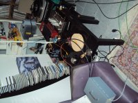
Is that a Clear Audio Compcet TT
I am looking for a TT worthy of the Paradise and that did came up as possible contender
with the Rega P9.
Joachim wuld you reccomend it and your impressions about it?
Is that a Clear Audio Compcet TT
I am looking for a TT worthy of the Paradise and that did came up as possible contender
with the Rega P9.
Joachim wuld you reccomend it and your impressions about it?