Yes, they are only "somewhere" alhough there are wormholes ( Einstein-Rosen Bridges ) everywhere.
Hesener, this is a good idea to notate P and N.
Hesener, this is a good idea to notate P and N.
I added 22r to R34 and the offset is the same +14v
Tp4 went from -12.5v to -12.2v
Q27 emitter went from -13.1v to -12.7v
Just to be sure I added more 22r to R34 (now total 220+22+22) and the offset keeps +14v
Tp4 went to -12v
Q27 emitter went to -12.6v
So this is not the solution.
(In the good channel I have tp4 = -12.53 and Q27 emitter = -13.1v and it works.)
Last edited:
Hesener, the offset is the same with or without the opamp... I even swaped opamps (from the good channel) and the situation is the same.
How can I check Q7, Q6 and Q24?
I will now remove the 22r and start measuring all the points.
How can I check Q7, Q6 and Q24?
I will now remove the 22r and start measuring all the points.
Yes, they are only "somewhere" alhough there are wormholes ( Einstein-Rosen Bridges ) everywhere.
Hesener, this is a good idea to notate P and N.
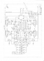
This is what the friends from ATL have to say
Attachments
10k trimmer on R8
reducing trimmer value, reduces offset from +14 to +13.3v seady
reducing even further offset starts to jump between +1 and -1
reducing further stabilizes offset in -13.3v
PS: There is no trimmer in R4 (I experimented there and the variation in offset also affected +Vin that was reduced from 24 to 20 and the trimmer went hot)
Last edited:
With the trimmer on R8, offset oscilates beteen -5 and +4v now... very difficult to keep the values low.
Hesener, the offset is the same with or without the opamp... I even swaped opamps (from the good channel) and the situation is the same.
How can I check Q7, Q6 and Q24?
I will now remove the 22r and start measuring all the points.
on q7, q6 and q24, i was just wondering if they are correct polarity.
but from your later posts i have a suspicion that your servo is not working. can you check the output resistors ? when you vary the trimmer, you should see the output voltage of the servo opamp swing from positive rail to negative rail or vice versa - this would indicate that the servo output has no impact on the balance of the amplifier.
or, maybe the 1Mohm input resistor of the servo is not ok. also, please note the feedback cap of the servo is 1uf not 100nf (wrong indication on the pcb). you can check the voltage on pin 2 of the opamp?
good luck
Check also that the PSU voltage at the servo after the Leds is not more then 18V at pin 4 and 7.
yes
on the good channel I read 1.4v and 2.5v on the same resistors
in the bad channel i read 15 and 16 not steady
on the good channel I read 1.4v and 2.5v on the same resistors
in the bad channel i read 15 and 16 not steady
Last edited:
Around 2V is optimal so the good channel is just fine.
The servo hits the end stops in the bad channel and can simply not supply more voltage.
Here is something very wrong. i simply have no idea what that could be.
The servo hits the end stops in the bad channel and can simply not supply more voltage.
Here is something very wrong. i simply have no idea what that could be.