What i can tell you is that the vias are made my manually inserting rivets. They are soldered in and then bored open so the resulting hole is nicely round. This is a lot of work.
Joachim,
Bungard has some very nice copper rivets (from 0.6 OD to 1 OD) which already have the bores done for you.
Just need to rivet and then solder.
Patrick
Bungard has some very nice copper rivets (from 0.6 OD to 1 OD) which already have the bores done for you.
Just need to rivet and then solder.
Patrick
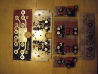
The tin plated PCBs look great (like in old HP measurement gear).
How can one do this at home ?
Tin plating cristals from various supliers
RS Part number is 567812
But normaly you may get them much cheaper somewhere else
RS prices are baad
There is also an alternative method but a kit is needed
It uses a power suply and same special electrodes and liquids
and can do silver or gold if I remember corectley it was designed to plate mobile phones and such.
I have not tried this but the tin plating cristals work fine
Just make what you need if you do not use regularly as solution losses propities with time.
EUVL, Klaus told me that his rivets are open too to start with but there can get some solder in so he bores them open so that the are nice and clean. Anyway, thanks that you seem to like what you see.
TDK has a new affordable turntable. It looks really good. In the music video you can see a woman smoking and playing a vinyl record. My kind of girl.
Belt Drive Turntable
Belt Drive Turntable
Thanks for the information on the tin plating crystals. Yes, it ain`t no cheep but it´s a big package.
http://docs-europe.electrocomponents.com/webdocs/001e/0900766b8001e68f.pdf
http://docs-europe.electrocomponents.com/webdocs/001e/0900766b8001e68f.pdf
Joachim,
> Anyway, thanks that you seem to like what you see.
Yes, graphics design is another hobby for me, and it also shows in my PCBs.
BTW if you use Bungard photosensitive boards for prototyping, I know a trick to use the resist as solder mask.
Please email if you'd like to know more.
Patrick
> Anyway, thanks that you seem to like what you see.
Yes, graphics design is another hobby for me, and it also shows in my PCBs.
BTW if you use Bungard photosensitive boards for prototyping, I know a trick to use the resist as solder mask.
Please email if you'd like to know more.
Patrick

I tell you more about the simulation i posted on your thread after the weekend. I have an important guest from today.
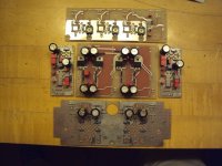
The board on the left must be for RCA´s right ?
I see you use the same GND for all of them.
Why so many ?
I see you use the same GND for all of them.
Why so many ?
The left PCB is the input and output PCB. The RCA`s are directly fixed to the PCB so the ground is not soldered and does not go though several metal contacts. I need 6 RCA`s for MC, 4 for input, 2 for optional loading of the trasconductance input. The loading components are then in external RCA jacks.Therefore the additional pair of RCA´s. The MC input is switchable between transimpedance and transconductance.For this i need 4 RCA´s. Loading of the transconductance input can also being done with on board Dil switches or both. The MM input has also 4 jacks for the same purpose. The onboard Dil switches are in this case responsible for switching in loading caps. There are some exotic MM´s that like to be loaded less the 47kOhm. That can be done with the external RCA´s. The rest of the RCA´s are the output so we have 6 for MC, 4 for MM and 2 for output for a total of 10.
The natural input impedance is 10 Ohm for the transimpedance input, 47kOhm for transconductance and MM.
The natural input impedance is 10 Ohm for the transimpedance input, 47kOhm for transconductance and MM.
Thank you Joachim
So you plan to use some RCA´s for external loading... Maybe with special RCA jacks with resistors / caps inside ?
Using the same GND for all input / output means you do not mix GND in the circuit wright ?
So you plan to use some RCA´s for external loading... Maybe with special RCA jacks with resistors / caps inside ?
Using the same GND for all input / output means you do not mix GND in the circuit wright ?
Yes, i saw that loading type first in a CAT preamp. Some people say that DIL´s sound bad so it circumvents that problem too when you put the DIL´s in the zero position. On the other hand a phono stage has to be complete with loading option when delivered, hence the way we designed it.
It is a ground plane construction but with a double mono PSU.
In a strict sense this is no star grounding.
It is a ground plane construction but with a double mono PSU.
In a strict sense this is no star grounding.