You're right, Rb in the FZT models is just 0.023. I changed it by adding this to the schematic:
.model FZT849_N ako: FZT849 Rb=8
And using FZT849_N as the LTP transistors. Rb=8 is just a guess, I don't know what it's supposed to be for these transistors.
Even then, the source impedance of 12 ohms is still the largest noise source, by 5 times or so. This is just about right. The circuit is advanced enough to not have significantly more noise than the source, but not overkill.
Learned something new again, thank you. I have no idea about their rbb, the lowest I saw documented is 1.6 Ohms or thereabouts for 2SC2547. And the 12 ohms source impedance come from my MC system. There are systems of 5 ohms, and maybe even lower.
Problem is that noise may be cancelled in the LTP, but it just doesn't, CCS based circuits just come out quieter when you build them. Try for yourself and listen
Problem is that noise may be cancelled in the LTP, but it just doesn't, CCS based circuits just come out quieter when you build them. Try for yourself and listen
Maybe the problem is in the power supply, with a very clean power supply there is no difference between resistor or ccs in the input stage, a CCS may have more PSRR.
In this type of circuits a very quiet power supply is very important, capacitance multipliers are very good for this.
One thing that is also important is the connection to the mains, I use a class II transformer without connection to safety ground, I have good result but I dont know if is the best solution, One thing that I thought was to use a transformer with a electrostatic screen connected to the main safety ground and with the secondary of the transformer isolated from the safety ground, I think will be better for preventing ground loops, but I dont know if is legal to have the secondary not connected to ground, the electrostatic screen will be a good protection in case the primary isolation fails.
.model FZT849_N ako: FZT849 Rb=8
And using FZT849_N as the LTP transistors. Rb=8 is just a guess, I don't know what it's supposed to be for these transistors.
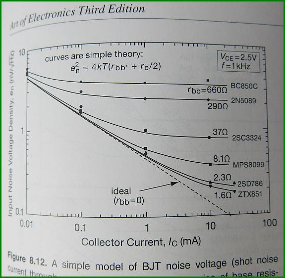
The rbb is less than 2 ohms at 10mA
Ignore my comment on how the plot might have been generated.http://www.diyaudio.com/forums/attachments/analogue-source/529322d1454629603-mpp-ztx-noise.jpg
those curves are shown for the formula quoted.
If the Rbb is the value as stated then the curve is as drawn.
I don't think that the curves are stating that the Rbb shown are typical for these devices. Does H&H shown the derivation of Rbb for those transistor types?
The plot is the result of measurements of noise of actual devices.
see Winhill2 post.
http://www.diyaudio.com/forums/soli...low-noise-transistors-gone-4.html#post4618356
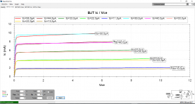
I put the ZTX851/951 pair on the curve tracer.
The result is very promissing.
Without searching much i found a well matching pair.
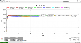
Early votage of the PNP is high and there is good Hfe linearity.
The graph shows both transistors overlayed.
The result is very promissing.
Without searching much i found a well matching pair.
Early votage of the PNP is high and there is good Hfe linearity.
The graph shows both transistors overlayed.
Attachments
Thank you, do you have a feel for them, compared to the biss I tested. I really like the biss, they seem very crisp in their presentation.
Not yet.*I have not build anything with them. What exact BISS types do you use ?
Maybe today i publish some noise measurements against my refference.
Maybe today i publish some noise measurements against my refference.
I just fixed these C1845/A992 models and also came up with a MPSA18 model with realistic noise and frequency behavior.
.model MPSA18_kn NPN(Is=100f Xti=3 Eg=1.11 Vaf=100 Bf=2.365K Ne=1.579
+ Ise=166.7f Ikf=.1172 Xtb=1.5 Br=5.774 Nc=2 Isc=0 Ikr=0 Rc=1
+ Cjc=4.948p Mjc=.4109 Vjc=.75 Fc=.5 Cje=13.6p Mje=.3765 Vje=.75
+ Tr=800.3p Tf=300p Itf=0.8 Vtf=6 Xtf=35 Rb=750 Kf=0.76f
+ mfg=OnSemi Vceo=45 Icrating=200m)
.MODEL KSC1845E_kq npn IS=1.075431E-13 BF=600.7 NF=1 BR=13.565 NR=1
+ ISE=1.98107E-13 NE=2 ISC=1.8378E-11 NC=1.5 VAF=82.803 VAR=20.6691
+ IKF=55m Nk=0.66 IKR=0.0190546 RB=157 RBM=12.092 IRB=1.258925E-6 RE=1.5
+ RC=1 CJE=18p VJE=0.7300286 MJE=0.3619943 FC=0.5 CJC=4.525739E-12
+ VJC=0.5 MJC=0.3659045 XTB=1.7281 EG=1.1809 XTI=3 Tf=420p Itf=20m
+ Xtf=1 Rco=250 gamma=2u Vo=500 Vceo=120 Icrating=50m mfg=Fairchild
.MODEL KSA992F_kq pnp ( IS=5.7544E-14 BF=348.1 NF=1 BR=3.62 NR=0.95
+ ISE=5.7544E-15 NE=1.5 ISC=1.8378E-14 NC=1 VAF=50 VAR=16.68 IKF=0.298
+ IKR=0.0525 RB=140 RBM=16.084 IRB=1.4125E-3 RE=0.3 RC=100m CJE=13p
+ VJE=0.855 MJE=0.4104 FC=0.5 CJC=8.9251E-12 VJC=0.5 MJC=0.3497 CJS=0
+ VJS=0.8 MJS=0.33 XTB=1.2849 EG=1.1603 XTI=3 XCJC=0.3062 Tf=420p Itf=5
+ Xtf=.5 Vceo=120 Icrating=50m mfg=Fairchild Rco=100 gamma=200n Vo=500)
Who here knew that the MMBT6429 is a MPSA18 clone?
Last edited:
I often see some parameters quoted to 4, or 5, or even more, significant figures.
Is this necessary?
Does the accuracy of the model require some params to be very accurately specified?
Would 3 significant figures be good enough?
Would the model be good enough if all the params were stated to 2 sig fig?
eg.
.model ksc1845e states ISE=1.98107E-13
would ISE=2E-13 be good enough? or 1.98E-13, or 1.981E-13?
Last edited:
Yes, that would be good enough. No one needs or expects simulator models to be more than 50% accurate I think, so just 2 digits (23, 2.3, 230) is great where accuracy is concerned and should satisfy almost everyone.
The parameters in those models that have more than 2 digits were ones I didn't change.
If one really wanted, they could load a model library into Excel and reformat all the numbers to 2 digits. That is of course a lot of unnecessary work.
I just had a vision of a Utopian society where no one used integers anymore, all numbers were exponents of 10. We did it with resistors after all.
Today i tried hard to measure voltage noise in BJTs, value and spectrum.
Unfortunately my jig did not work as expected so i will try another option.
I will also post more measurements from the curve tracer.
Anyway, it looks that there are many options for a low noise BJT even if they are not advertised as made for phono MC.
There is also no shortage of fitting PNPs.
This is a much better situation then with J-Fets, especially P channel types.
How is HFE though? Will they need an input capacitor to block highish Ib going through the generator?
I have an input cap and i can arrange for collector current and Vce.
I have a noise problem so i will solder instaed of clips and i will use another input amp topology where i can measue NPN and PNP together.
It is a variety of the Curl Pre-Pre that worked some time ago.
I see interesting things on the spectrum but is is too early to speculate.
I also have a new pre-pre design i call the Tumble Weed Connection. It comes very close to the sound of a Lundahl LL1941. You will be shocked : yes, i like transformers when they are good. Maybe i am too old to hear loss in the higher reaches but 100kHz from the Lundahl is a word.