I think for MM we have to reduce the idle, from the standpoint of current noise and also because of the input impedance.
I have the RiAA Values for a 42-44 dB gain circuit. idle reduction can be done by alteration in in central CCS. What kind of current would you want through the input transistors..??
Personally I dont think anr current reduction is needed as the driving signal is so much stronger, the noise suppression will still be enoumous, but off course the input impedance will be an issue.
Personally I dont think anr current reduction is needed as the driving signal is so much stronger, the noise suppression will still be enoumous, but off course the input impedance will be an issue.
Last edited:
The " natural " input impedance of the Paradise is around 10kOhm.
That is too low for MM. I would like it to be at least more then 50kOhm.
The problem is that reduced idle will then also reduce the amount of current that we can dump into the RIIA worsening distortion. On the other hand we have lesss gain and that brings the performance back. Kind of juggling. We COULD of cause use Fets at the input with only a small change in topology.
Last edited:
I have the RiAA Values for a 42-44 dB gain circuit. idle reduction can be done by alteration in in central CCS. What kind of current would you want through the input transistors..??
Personally I dont think anr current reduction is needed as the driving signal is so much stronger, the noise suppression will still be enoumous, but off course the input impedance will be an issue.
Hey that wuld be just perfect for one of those...
http://www.acton-gate-audio.co.uk/p...li&ManufacturerName=Sumiko&ProductName=Sumiko Blue Point Special&ProductID=2903
Was tempted to get one especialy for the 35dB channel separation.
A new structure that could substitute tubes :
Electron field emitter technology to improve imaging, communications
Electron field emitter technology to improve imaging, communications
Vacuum transistors
There was recently a seminar where NASA researchers presented an overview of their work on vacuum tubes built on the nanoscale. Very interesting stuff. Slides here: http://sites.ieee.org/sfbanano/files/2013/01/SIVNano_0219_modified.pdf
---Gary
There was recently a seminar where NASA researchers presented an overview of their work on vacuum tubes built on the nanoscale. Very interesting stuff. Slides here: http://sites.ieee.org/sfbanano/files/2013/01/SIVNano_0219_modified.pdf
---Gary
I am back 🙂 .... I hope everybody is doing well.
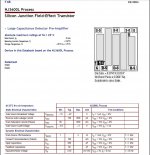
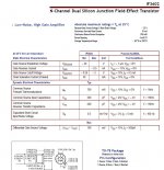
I got some data fir the IF3602 ...yes....the super Jfet.
I have 2 papers, one shows an Idss of 30mA another from 50mA to 1000mA which would seem to be basically terrible!
Also there are some plots shown and in order to reach out 250mS transconductance, Idss must be in the order of 300mA (!!!!)
Am I looking at it wrong?
Attachments
Something does not come from nothing.
Yes, i know, the data is not very consistent.
I heard that from Scott Wurzer.
Yes, i know, the data is not very consistent.
I heard that from Scott Wurzer.
do you mean the data sheet are wrong?
Has anybody ever tested one of those devices? I have some coming this week.
I really hope gm is what it says it is and current is not 1A....gosh!!!
Has anybody ever tested one of those devices? I have some coming this week.
I really hope gm is what it says it is and current is not 1A....gosh!!!
The data sheet does not say all we need, for example 1/F noise.
The high idle comes with the territory.
If you would parallel a lot of BF862 you end up with a lot of idle too.
The interesting question is if that Fet has massive Gm with less input capacitance then paralleled BFs.
The high idle comes with the territory.
If you would parallel a lot of BF862 you end up with a lot of idle too.
The interesting question is if that Fet has massive Gm with less input capacitance then paralleled BFs.
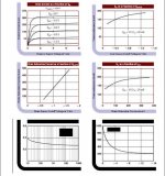
Drain current against voltage
looks really good.
This is a much better CCS then paralleled BFs.
looks really good.
This is a much better CCS then paralleled BFs.
Drain current against voltage
looks really good.
This is a much better CCS then paralleled BFs.
yes I noticed it too. I just can't understasnd what the Idss is.
As an input stage, if you think about MasterPiece R7, I will try this out, but if the devicce needs to be biased at 200mA to get high gm it will be extremely hard to design the CCS around and shunt PSU and keep everything electrical and thermally stable.
Hoever, from the characteristics I can see, it looks pretty really linear to me a good linear input stage.
The 1/f, you can kinda see the noise behaviour on one of the lot shown on page 2 of doc 1.
The y shows equivalent noise en and on the x frequency.
It looks like noise is kept very low even at low frequency to a point that noise behaviour looks more like a BJT than a JFET 😱 😱

Last edited:
I just found this about electrolytics.
Reforming Electrolytic Capacitors
Sorry, Stefanoo, this does not fit in our current discussion.
I found it interesting nevertheless.
Reforming Electrolytic Capacitors
Sorry, Stefanoo, this does not fit in our current discussion.
I found it interesting nevertheless.
Well, this week I will reveive the Jfet, I will try to test Idss and transconductance to begin with!
I am afrrais, since I can't really deduce it from datasheet that Idss varies largely and can get huge.
If that is the case this device would be useless given the high price tag to find matched pair for a stereo amp.
Also, like I mentioned if it needs 200mA of biasing to reach out 400mS or 750mS like datasheet says, then still makes it hard to use!
I just found this about electrolytics.
Reforming Electrolytic Capacitors
Sorry, Stefanoo, this does not fit in our current discussion.
I found it interesting nevertheless.
oh ok! Sorry for the interjection then.
I will let you continue without interjecting anymore. 😱😱
 😎
😎