So here it is 5 to 35V up to 1Amp, maximum dissipation at IRFP924 35Watt (when Vout 35Volt @ max 1Amp), and at each of the power transistors 17Watt (when Vout = 5Volt @ max 1Amp).
Tanks Frans
briliant that wuld make prety decent lab suply to try things out and most of all real good circuit to study and learn.
Arg. Billy Bragg
Was going to punch him good but his girl friend stepped in...
This was back in Italy in 1984 in Venice at Comunist Party party (similar like to bear fest thing)
Was going to punch him good but his girl friend stepped in...
This was back in Italy in 1984 in Venice at Comunist Party party (similar like to bear fest thing)
another typo? TL431 I think
Now I see what I need to do, I the dyslectic, I need to stop drawing these schema's and I must stop posting the results of my labor, I will make my life easy and I will have removed a lot of typo's from the forum 🙂
Please carry on with whit posting and don't worry about typos
I put them there on purpose at time to ensure full attentions 😀
(Those whose do not make are the one that use the spell checker)
If any one complain is the ignore bin.
(Got nice picture in this regard from other forum)
This is a hobby so loads of things we don't do at day Job should be allowed
The pressure relief valve stop working otherwise
And board will just be lifless piece of cooper
Attachments

Last edited:
I w's kin'da kid'ing, 's we say in Holland 🙂
"Waar gehakt wordt vallen spaanders"
P.s. Cool picture from a cool movie!
"Waar gehakt wordt vallen spaanders"
P.s. Cool picture from a cool movie!
"Waar gehakt wordt vallen spaanders"
Only on wednesday.
Don't happen to have a larger image of the LT413 power shunt ?
Please carry on with whit posting and don't worry about typos
I put them there on purpose at time to ensure full attentions 😀
(Those whose do not make are the one that use the spell checker)
If any one complain is the ignore bin.
(Got nice picture in this regard from other forum)
This is a hobby so loads of things we don't do at day Job should be allowed
The pressure relief valve stop working otherwise
And board will just be lifless piece of cooper
And now I also like the logo 🙂 😉

 😛
😛For everyone that has a bit too much time (as I apparently have 🙂) please go to http://www.diyaudio.com/forums/solid-state/209896-amplifier-dc-protection.html#post2967794 and check it out (sorry for the advertisement, but I need some/any/more input on this).
Attachments

Last edited:
I use NTE 7100 there are a few similar chips under other names with same function.
Those are obsolete and hard to get but still out of there.
I am going to have a look at it and try to understand it.
Other thing I use (I hope this is worty contribution) is the Amplimo relay that is designed for this purpose Loudspeaker relay - toroidal-transformer.com
Slight price difference to normal relay but stated DC breaking spec of 100A at 50V
Big difference from normal relays that are rated at AC and can not cope with the arking
that DC presents.
About Logo tanks just bit of fun for now (no commercial intent at present so I am not breaking copyrigts) let me know what best to put on board for when (and if ) gerbers are needed.
Last edited:
I use NTE 7100 there are a few similar chips under other names with same function
Is this a 'NO' or 'NC' (normally (unpowered) open or closed) relay, strangely enough the site does not show that information. Also there is no information on contact resistance, other that it being very low.
It is normaly open
About contact resistance I don't know
That be a good question to ask Amplimo
It may be that is embarasing for them to post number (not that low) but normaly the things they sell are prety ok.
About contact resistance I don't know
That be a good question to ask Amplimo
It may be that is embarasing for them to post number (not that low) but normaly the things they sell are prety ok.
It is normaly open
About contact resistance I don't know
That be a good question to ask Amplimo
It may be that is embarasing for them to post number (not that low) but normaly the things they sell are prety ok.
Plaese have a look at http://www.diyaudio.com/forums/solid-state/191449-output-relays-18.html#post2974843
I will draw now the new version of the Paradise.
The input will be virtually unchanged, the mirrors get an improvement, the RIAA gets Ricarrdos values, the complicated output buffer will be substituted with my floating cascode J-Fet buffer and Fans new PSU will be implemented. Hesener will make a new layout with all he learned debugging the orininal version.
The input will be virtually unchanged, the mirrors get an improvement, the RIAA gets Ricarrdos values, the complicated output buffer will be substituted with my floating cascode J-Fet buffer and Fans new PSU will be implemented. Hesener will make a new layout with all he learned debugging the orininal version.
I will draw now the new version of the Paradise.
The input will be virtually unchanged, the mirrors get an improvement, the RIAA gets Ricarrdos values, the complicated output buffer will be substituted with my floating cascode J-Fet buffer and Fans new PSU will be implemented. Hesener will make a new layout with all he learned debugging the orininal version.
Nice, thanks Joachim, we are 'on track' an still going ... 🙂
I like the Idea of solid state relay very much.
Many will not use relay contacts due to the possible degradation in sound that the large and clumsy contact needed cause
Solid state will certanly get around to that and be much faster in operation wheen needed.
I will need to take same time and start reading that tread.
Nice, I did not finish the regulators this weekend, I did destroy my new (currently being build) amplifier and took most of Saturday and a large part of Sunday to fix that. (I did made some re-wire errors after a small modification on the vero board).
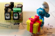
Now my regulator proto types will be finished by the end of this week. I am aiming for a board size of 4 or 5 cm2 (that is half of an square inch).
And, yes, the transistors need a heatsink (5 to 10 deg/watt).
P.s. This design is not intended for the Paradise (it is to under powered for that).
P.s. This design is intended for amplifiers that may have a few, 2 or 3, opamps that need to be fed from the amplifier supply at up to 80 volts.
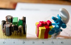
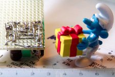
Here is one, the mini ATL PSU + side. About 5 cm2 🙂