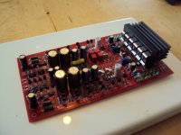
The first Shunt is mounted. It is a bit tricky to adjust the "legs" but it is possible.
beautiful!
The first Shunt is mounted. It is a bit tricky to adjust the "legs" but it is possible.
But does it work (now you would like those bridges 🙂)
P.s. Is that one leg in the neck 🙂
Last edited:
Yes, that PCB comes out looking nice, no matter how you stuff it.
No, Frans, it is not working yet. I go the Ricardo all in one way, love me or leave me.
No, Frans, it is not working yet. I go the Ricardo all in one way, love me or leave me.
Yes, that PCB comes out looking nice, no matter how you stuff it.
No, Frans, it is not working yet. I go the Ricardo all in one way, love me or leave me.
You know what


Yes, that PCB comes out looking nice, no matter how you stuff it.
No, Frans, it is not working yet. I go the Ricardo all in one way, love me or leave me.
I used a lab supply with both voltages tracking to power up, and the Paradise should draw 150mA each rail. If it doesnt, or the supply voltages after the shunts go above +/-24V its time to power back down.... didnt happen to me though.....
Just waiting for feed back I had no chance to buid proto so far
I have posted 2 boards one with diodes lined up on long side which my be better for my own build.
If FDW let me know first impressions and further changes needed I be more than happy to carry on.
I have posted 2 boards one with diodes lined up on long side which my be better for my own build.
If FDW let me know first impressions and further changes needed I be more than happy to carry on.