I need enough crossover and opamp boards to make a balanced,
12 dB, low pass filter. I think that means 4 boards....
Don't forget Roddy- he'll order anything...
12 dB, low pass filter. I think that means 4 boards....
Don't forget Roddy- he'll order anything...
Hi there,
I don't wanna get flamed here, I'm merely looking for opinions.
I just tought that perhaps we could replace the relays with analog multiplexers. That would allow anyone to control the slopes/frequency with 2 or 3 multiplexers on each boards. Multiplexers could be controlled easily by a microcontroller or even jumper, lowering the jumper count required (not that jumpers are expansive or anything).
The multiplexer could be something along the lines of this one:
http://www.fairchildsemi.com/pf/MM/MM74HC4051.html
If not, then fine I'd still want a few boards myself (around 12 high pass and 12 low pass)
Sébastien
Why not keep the relay/mutiplexor option as separate boards?,
the same way as the op amp is separate. I guess thats a lot of wiring though... I just want the jumpers and need to keep it simple and cheap.
the same way as the op amp is separate. I guess thats a lot of wiring though... I just want the jumpers and need to keep it simple and cheap.
Actually, here, multiplexers are cheaper than jumpers (no kidding). And you're right, I probably could do some simple daughter boards that would allow me to put the multiplexers into the slots designed for jumpers (they could probably also mount on the jumper pins provided that I find a proper socket)
Actually a daughter board could be done for relays providing a maximum of flexibility.
That needs more tought than I currently have the time for.
Does anyone have an opinion about the multiplexer in terms of sound?
Sébastien
Actually a daughter board could be done for relays providing a maximum of flexibility.
That needs more tought than I currently have the time for.
Does anyone have an opinion about the multiplexer in terms of sound?
Sébastien
I think that the existing design is great as it is. If it is to be controlled via relays, an expansion board could be created that simple plugs into the header pins where the jumpers go. This way, you could just stack the boards up, putting the microcontroller/relay board on top of the existing board, and if you want to do it manually, just don't use the relay board. I was thinking about doing this, as it would be quite flexable. But my idea was to use cmos switches instead of relays, since they are smaller, and analog devices makes some ones made for audio. This would also keep the same footprint.
just an idea... realistically, I wouldn't change my settings much, but during the prototyping process, you could set various settings on the jumpers with the microcontroller, and save them, allowing you to jump back and forth between different slope filters to see what sounds best.
This would be a fun product for prototyping, then once you settle on the settings that you like, you could unplug it and use normal jumpers to simplify the signal path.
--
Brian
Well Brian, you said it all. This is exactly along what I was thinking. If it comes to life, this would make a really nice project for any speaker building enthusiast!
Sébastien
Sébastien
Who, where, what ever it is, I'm in.😀Variac said:Don't forget Roddy- he'll order anything...
tool49 said:Well Brian, you said it all. This is exactly along what I was thinking. If it comes to life, this would make a really nice project for any speaker building enthusiast!
Sébastien
Thanks, if no one does it first, I will make my own in a couple of months.
--
Brian
tool49 said:Actually, here, multiplexers are cheaper than jumpers (no kidding). And you're right, I probably could do some simple daughter boards that would allow me to put the multiplexers into the slots designed for jumpers (they could probably also mount on the jumper pins provided that I find a proper socket)
Actually a daughter board could be done for relays providing a maximum of flexibility.
That needs more tought than I currently have the time for.
Does anyone have an opinion about the multiplexer in terms of sound?
Sébastien
You could very easily mount the relay board on a separate board in the same plane as the main filter board and connect them with ribbon cable and IDC connectors.BrianGT said:I think that the existing design is great as it is. If it is to be controlled via relays, an expansion board could be created that simple plugs into the header pins where the jumpers go. This way, you could just stack the boards up, putting the microcontroller/relay board on top of the existing board, and if you want to do it manually, just don't use the relay board. I was thinking about doing this, as it would be quite flexable. But my idea was to use cmos switches instead of relays, since they are smaller, and analog devices makes some ones made for audio. This would also keep the same footprint.
just an idea... realistically, I wouldn't change my settings much, but during the prototyping process, you could set various settings on the jumpers with the microcontroller, and save them, allowing you to jump back and forth between different slope filters to see what sounds best.
This would be a fun product for prototyping, then once you settle on the settings that you like, you could unplug it and use normal jumpers to simplify the signal path.
--
Brian
I not particularly for the idea of relay control of the slopes, corner frequencies, et al. Having lived with electronic x-overs for the past 20+ years, I would be happy with multi position switches. A remote level control is the possible exception, but not a necessity. Also don't forget Moamp's warning to Raka on the last page.
moamp said:...be carefull with on line resistors and capacitors switching, using some temporary outputs muting circuitry is recommended.
OK, folks, I have set up a Wiki for those who are interested to get some pcbs, so that we understand demand and quantity and costs of boards better:
http://www.diyaudio.com/wiki/index.php?page=MOX+
I would like to encourage you to signal your demand for the boards, so that we understand better about what business we are talking. As a couple of questions are still open (final board design, who will actually manage the distribution and money collecting etc), this is not an order yet, so don't ask for price etc, just help to understand the demand.
Best Regards
An idea
Hi great work with the filter,
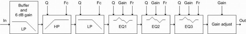
My idea is to make one PCB with a BP filter and some EQ sections. The band pass filter has selecteble fc and Q.
The EQ sections can be boost or cut, and can have different Q fres and gain.
For a two way filter use two modules, and so on.
Tell me what you think
Like this:
Hi great work with the filter,
My idea is to make one PCB with a BP filter and some EQ sections. The band pass filter has selecteble fc and Q.
The EQ sections can be boost or cut, and can have different Q fres and gain.
For a two way filter use two modules, and so on.
Tell me what you think
Like this:
Attachments
I think, that's great. I always wanted to have a cross-over which can boost the super-treble of my Philips Magnetostat from 15khz on. It would be great to have the right level of adjustment on these Eq like here: http://www.thel-audioworld.de/pics/tc2000.gif
For the full desciption please read the (german) site:
http://www.thel-audioworld.de/module/tc2000/tc2000.htm
So basically you can adjust frequency, level of boost and width.
Best Regards
For the full desciption please read the (german) site:
http://www.thel-audioworld.de/module/tc2000/tc2000.htm
So basically you can adjust frequency, level of boost and width.
Best Regards
Blitz said:OK, folks, I have set up a Wiki for those who are interested to get some pcbs, so that we understand demand and quantity and costs of boards better:
http://www.diyaudio.com/wiki/index.php?page=MOX+
I would like to encourage you to signal your demand for the boards, so that we understand better about what business we are talking. As a couple of questions are still open (final board design, who will actually manage the distribution and money collecting etc), this is not an order yet, so don't ask for price etc, just help to understand the demand.
Best Regards
Blitz,
I would remove all reference to the XVR1, as it is a commercial product, and this design is not fully identical to Nelson's design, and I would not want this diy version misrepresented as such.
I would refer to this design simply as a active crossover implemented Butterworth filters, with a discrete opamp stage.
--
Brian
There, I removed the references in the Wiki. I agree with it not needing to be associated with the commercial product. It is a product on its own.
Sébastien
Sébastien
One question to moamps: Have you compared the sound of the dicrete opamp with the sound of the very best ready-to-use-opamps out there ?
Blitz said:Yup, was not meant in that way, but no problem. Done.
tool49 said:There, I removed the references in the Wiki. I agree with it not needing to be associated with the commercial product. It is a product on its own.
Much better, definately a product on it's own, especially considering that there isn't any patented technology in it.
--
Brian
Blitz said:One question to moamps: Have you compared the sound of the dicrete opamp with the sound of the very best ready-to-use-opamps out there ?
Hi,
only with NE5534 and TL071. Discrete OPAMP sounds better.
Regards
- Status
- Not open for further replies.
- Home
- Source & Line
- Analog Line Level
- MOX - active crossover