tiroth,
this is all new to me so before ordering i was wondering if you would publish, apart from the schematics, some sort of manual for component placing and other recommandations,
regards
this is all new to me so before ordering i was wondering if you would publish, apart from the schematics, some sort of manual for component placing and other recommandations,
regards
Just a quick thought...
Can you configure the input buffer so it could be used as a virtual earth mixer? Just makes using it as a sub crossover a little more straightforward.
But then again, that would mean running it as inverted...
😉
Can you configure the input buffer so it could be used as a virtual earth mixer? Just makes using it as a sub crossover a little more straightforward.
But then again, that would mean running it as inverted...
😉
kepa1 said:
this is all new to me so before ordering i was wondering if you would publish, apart from the schematics, some sort of manual for component placing and other recommandations,
Tiroth,
Likewise, I would apreciate any further info.
Regards, APK
pinkmouse,
That's a good idea. There is no problem with the topology, since the inverting input is already "free" for use as a balanced input. I'll see if I can squeeze some additional pads in to accommadate the extra resistors and inputs.
kepa1+APK,
I will be creating a stuffing guide. I'll post some more info on my site tonight.
Order form
http://tiroth.brinkster.net/mox_order2.html
Member
Joined 2002
I was just wondering if you have any spare / boards that are just for low pass xover's. I need something simple for a cut off of 100hz and down.
J'
J'
Will the OPAMPS be biased into Class A operation?
I placed my order through PayPal.
Regards
Anthony
I placed my order through PayPal.
Regards
Anthony
Coulomb,
I'm guessing you are referring specifically to the discrete opamp--that design always operates in Class A by default.
I'm guessing you are referring specifically to the discrete opamp--that design always operates in Class A by default.
tiroth said:Coulomb,
I'm guessing you are referring specifically to the discrete opamp--that design always operates in Class A by default.
Doh! 🙂
Thanks for the quick response.
Anthony
I have partially recovered my site from backups. I will work next on recovering the images in the opamp assembly guide and writing the the MOXlite assembly manual. Jens has been a big help with this -- thanks Jens!
Please do not be alarmed when the order form redirects to this page:
http://www.anidian.com/audio/construct/mox_order.shtml
Please do not be alarmed when the order form redirects to this page:
http://www.anidian.com/audio/construct/mox_order.shtml
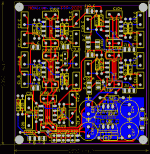
Tweaked layout, including a total of 4 potential inverting inputs for bass management usage. Other changes included routing improvements and overlay changes for readability.
http://www.anidian.com/doc/moxlite_v21_board.pdf
http://www.anidian.com/doc/moxlite_v21_board.pdf
tiroth said:Tweaked layout, including a total of 4 potential inverting inputs for bass management usage. Other changes included routing improvements and overlay changes for readability.
BROKEN LINK REMOVED
Hummm Page Cannot be found.
Anthony
moxlite
Any chance of including some way of simply changing the gain of a channel, on board preset pot for one or preferably two output or similar?
Ross
Any chance of including some way of simply changing the gain of a channel, on board preset pot for one or preferably two output or similar?
Ross
tiroth,
what would it take for a balanced output?
i read it can be "tweaked" on the mox PCB but what about integrating it on the PCB now?
also, what is the actual size of the moxlite PCB?
regards
what would it take for a balanced output?
i read it can be "tweaked" on the mox PCB but what about integrating it on the PCB now?
also, what is the actual size of the moxlite PCB?
regards
Size: The boards are 3.09"x2.9" (79mmx74mm)
On-board pots: I have added space for a 3-terminal pot on each channel. There is limited functionality from this though--this will work great if you have the amp in the same box, but it won't be useful if you need a line driver, because there is no buffer after the pot.
Balanced out: I'm sorry, but this board just isn't going to support balanced out. Using normal opamps the size of the board would increase almost 100%, and even using something like DRV134 it would be 50%. All is not lost, though--pseudo-balanced works fairly well in most cases, especially if you have a high quality receiver.
Of course, one could always add buffers or balanced drivers on a small protoboard.
Here is the new layout. The ground plane is moved because it is a pain to keep ripping it up for each change.
http://www.anidian.com/doc/moxlite_v22_board.pdf
Attachments
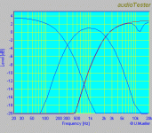
Here are the actual measurements from the prototypes. This is for a real set of active loudspeakers
Low pass: 320Hz, Q=0.5
Band pass: 320-3200Hz, Q=0.5
High pass: 1600Hz, Q=0.5
The red trace shows the high pass output, the blue trace shows a parametric notch filter centered at 12kHz, gain -3dB, Q=4.
I can see from the HF measurement that I need to reduce the ground fill a bit around the HP section. I thought that simply moving to a single-side fill would be enough, but I can see there is still a little too much stray capacitance.
Attachments
Tyler,
Nice work 🙂
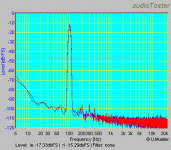
What's the problem with the groundplane? does the measurement not match the calculated response?
I did some experiments with my filter one board and found that the calculated response matched the measured nicely.
Please explain further
\Jens
EDIT: added image
Nice work 🙂
What's the problem with the groundplane? does the measurement not match the calculated response?
I did some experiments with my filter one board and found that the calculated response matched the measured nicely.
Please explain further
\Jens
EDIT: added image
An externally hosted image should be here but it was not working when we last tested it.
- Status
- Not open for further replies.
- Home
- Group Buys
- MOX active crossover buy


