Bonsai said:For lowest noise in an MC or MM amp it has to be single ended.
For lowest amplifier voltage noise you do indeed need to be SE. A differential input has double the noise power (3dB), or 1.414 times the noise voltage of an SE design using the same device.
The difficulty with SE designs is that you can only get the correct DC operating conditions by using at least one, and usually two, electrolytic caps. My own preference is to accept the 3dB noise penalty, and use DC coupling throughout the design.
But this only matters for fairly low impedance MC sources. For MM (or high impedance MC) the Johnson noise in the source can easily vastly exceed the amplifier voltage noise.
The way I think about this is by considering noise resistances. A 1 Ohm resistance gives 0.13nV/rtHz of noise - and this rises with value as sqrt(R). The quietest op-amps (like LT1115, LT1028) are round about 0.7 to 0.8nV/rtHz which is the same as the noise in a 30 Ohm resistor. A low output MC is a few Ohms in resistance. Clearly, we want the feedback network to have a shunt resistance that is in this range; certainly no more than 20Ohms.
A rough approximation for semiconductor devices is to say that the noise resistance is the inverse of the transconductance + any input spreading resistance. For bipolars, this gives Rn is roughly Rbb + 26/Ic where Rbb is the base spreading resistance, and Ic the collector current in mA. To do as well as the best op-amps a SE discrete circuit needs to run about 1mA in its input device for an ideal device; a differential circuit needs to use 2mA in each leg.
If you want transistors with low rbb, I would suggest the Renesas 2SA1084 / 2SC2546 - they also have very low 1/f noise, which is another story.
Interestingly enough, the effective R noise for a bipolar transistor is r(e)/2. It is not directly connected to the Gm of the device, but a product of second stage shot noise divided by the Gm and referred to the input. This would appear unlikely, at first glance, but it means that it is easier to achieve very low noise, than Gm alone, would imply.
For jfets, it is 2/pi rather than 1/2, ideally. It usually is a little worse due to 1/f and other factors.
For jfets, it is 2/pi rather than 1/2, ideally. It usually is a little worse due to 1/f and other factors.
I hope that I didn't scare everyone off with my input. It is only that low noise design is a little more complex in the understanding of the basic mechanisms than simple intuition would suggest. However, the formulas are out there to use, and they will work!
For example: The basic noise of a fet is 2/3 times 1/Gm. Why, I don't remember, but there is a good quantum mechanical reason.
For a transistor with a LOW input impedance:
The effective noise RESISTANCE IS: Rbb' {that is base resistance made at manufacture} + 1/2Gm {which is set by the collector current}
For example: At 2.7ma, a very good transistor might have a noise resistance of:
2 {Rbb'}+10 {1/Gm}/2= 7 ohms Pretty darn good. That is about 0.35nV/rt Hz.
For a fet at 10ma: It might be .66 times 1/.025, which might be about 25 ohms
I have just designed a pre-pre with 0.6 nV/rt Hz of voltage noise
and 32dB gain using a bjt (front-end) and a opamp 5534 , but you can use several opamp.
and 32dB gain using a bjt (front-end) and a opamp 5534 , but you can use several opamp.
The pre-pre should have balanced inputs to minimise hum pick-up.
Not necassarily. I tried once balanced, no improvement.
Hi, I hate transformers in the signal path!
Not me. I have made dozens of pre-pre, pretty much all what is found on the web, still prefer ortofon step-up trafo for the sound.
john curl said:I hope that I didn't scare everyone off with my input. It is only that low noise design is a little more complex in the understanding of the basic mechanisms than simple intuition would suggest. However, the formulas are out there to use, and they will work!
For example: The basic noise of a fet is 2/3 times 1/Gm. Why, I don't remember, but there is a good quantum mechanical reason.
For a transistor with a LOW input impedance:
The effective noise RESISTANCE IS: Rbb' {that is base resistance made at manufacture} + 1/2Gm {which is set by the collector current}
For example: At 2.7ma, a very good transistor might have a noise resistance of:
2 {Rbb'}+10 {1/Gm}/2= 7 ohms Pretty darn good. That is about 0.35nV/rt Hz.
For a fet at 10ma: It might be .66 times 1/.025, which might be about 25 ohms
I think the big real world "gotcha" to add to this is 1/f noise. Although the ear is not very sensitive to LF noise (Fletcher Munson curve), the RIAA curve supplies 20dB of LF boost, which pretty much wipes out the subjective weighting advantage. Transistors vary a lot in terms of 1/f noise; typically epi processes are quieter.
As a rule, FETS tend to do worse.
Note that capacitor coupled designs tend to have an additional LF noise rise, unless truly gigantic coupling caps are used.
Operating multiple parallel devices at a lower current per device can get to very low noise of all sorts, but rapidly gets expensive, and vastly increases the capacitances - and remember they are voltage dependent non-linear capacitances.
My own preference, used in the only commercial product I designed, is to go with complementary differential pairs of the Renesas bipolar transistors, run at about 1.5ma per device. The input and feedback are DC coupled. This gives an overall noise floor of about 0.5nV/rtHz, comfortably better than the best monolithics, with some mild cancellation of input bias current (which is low as the Hfe is so high in the chosen devices).
Toshiba jfets can be very quiet. Just look at the data sheet. They give a complete noise curve. Of course, 1/f noise is important, but the ear falls off VERY fast below a few hundred cycles and it is difficult to hear. Just look at a CCIR ear weighted curve.
Accurate measurement of effective noise is somewhat difficult do to excess 1/f noise contribution, except that many THD analyzers have an 18dB/oct, 400Hz filter. This is useful in this case, for more than just hum rejection.
I have made both fet and bipolar MC amps, over the decades. It is fairly easy to get about the same noise with either choice. I usually work to 0.4nV/rt Hz, or the equivalent noise of a 10 ohm resistor.
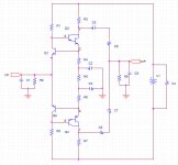
In response to Echo Wars I have attached a generic schematic of the Rossiter preamp for discussion purposes (no values).
It's an elegant design, and answered most of the original criteria when I started the thread:
1) Direct coupled to the cartridge
2) Input impedance defined by the active components and not by a shunt resistor wasting power from the source
3) Very low net DC current in the cartridge (requires good match of input transistor hFE)
4) Very low noise - using the recommended 2SA1316 and 2SC3329 complementary pair at 5mA gives Ein of approx 0.4nV/rtHz. This was better than the Ortofon dedicated preamp MCA76 for the Ortofon MC20 cartridge.
At the time I built the preamp, I had access to a Rohde and Schwartz UPV audio analyzer, maybe the best on the planet. Not many can cope with a 10 ohm input impedance amplifier! I may post some of these results later.
Attachments
this post is very interesting and so informative.
Great insight!
I am trying to build a MC phono amp as well and i would love if i could receive some comments on my choices below described.
1) pick-up used will be the Denon DL-103
2) I am planning on use the common paralleled (maybe 5 or 6 paralleled or more?!) source JFETS configuration with 2sk170BL as John kindly suggested for the input MC stage only output coupled with 1uF/220kohm cascoded with a low noise BJT to shunt down the input capacitance.
3) For the next stage i have chosen the classic differential amp made by 2sk389BL and current mirrors with push-pull output stage; i am trying to manage to not have a large electrolytic on the feedback network that fixes a unity DC gain.
This operation requires lots of cares in terms of thermal stability as far as my experiments with the prototype on the breadboard i have built are concerned .
Output will be cap coupled through the high pass 1uF/220Kohm
4) I decided to split RIAA equalization network in active on the feedback network of the MM stage from output back to the minus input of the differential amplifier and passive equalization (75uS time constant only) between the output MC and the input of MM stage to maximize noise performance and to manage a more precise network.
5) The preamp will only be used as MC with the cart Denon DL-103 as specified on point (1).
6) I am going to use separate power supply for the MC part and MM stages; the topology chosen for the power supply is the Shunt to guarantee very low noise.
7) The MM part will be supplied at +/-30V, whilst the MC at 38V or so.
The higher voltage is chosen to allow me to put as gain as possible (reasonably speaking) on the common source stage and to have enough voltage swing to put the JFETS on the "good spot" VDS 10V or so.
Drain resistor will be 890ohm-1kohm whilst source resistor will be 3.3ohm for a total gain of 43dB with 5 paralleled devices.
Gain on the MM part will be around 22dB.
I have chosen a "low" gain for the MM to minimize the issues of DC output drifting and to achieve a lower noise.
If i can, i have few questions below:
a) Does the common source stage tend to sound worse with more gain set than at a lower gain?
b) I have noticed that the MM part alone doesn't have any significant DC drifting (under 1mV).
Nevertheless when the MC stage is connected the DC starts to drift significantly (i've managed with a plastic ball on the circuit a drifting of about 6-7mV sometimes i see it going up to 12-18mV for a fraction of a second).
So i measured the drifting of the MC and it's around 0.2-0.3mV.This data makes up with the drift i measure at the output since DC gain of the MM is around around 110.
Is there any way i can get a better DC performance from the common source stage?
What is a decent/acceptable DC offset for a MC preamp?
c) another issue i am noticing is with DC transient at the output at the turning on and off moment.
This is majorly due to the common source stage which is supplied by a single positive supply.
Is there any way to get rid of these transients somehow without having to use output relays or muting transistors?
In case it is not possible: what is the most purist sulution? output relays or muting transistors? (i would be inclined to think the latter one)
Alright...thank you folks for the attention paid.
I Hope everybody will have a great day.
Best,
Stefano
For muting, choose relays over transistors.
When designing your MC stage, be careful about avalanche noise; some active devices show an extra noise process when they have more than about 10V or so on them, so try to keep the voltage on the input devices reasonably low, perhaps by using some sort of cascode or other trick. At the very least, do some measurements to prove that it isn't a problem for your circuit.
When designing your MC stage, be careful about avalanche noise; some active devices show an extra noise process when they have more than about 10V or so on them, so try to keep the voltage on the input devices reasonably low, perhaps by using some sort of cascode or other trick. At the very least, do some measurements to prove that it isn't a problem for your circuit.
if you look a the data-sheet for the 2sk170, perhaps you are referring to this thing, the last graph shows the excess current for specified VGS.
The current seems to be fairly low and in order to have a significant effect VDS would have to be raised enough.
I like to run jfets at higher VDS 7-8 i think they sound better.
Higher VDS also puts you on the better flatter pinch off region, lowers the input capacitance.
Cascode will certainly help the input capacitance when many devices are paralleled to achieve higher gain and lower noise as well as bandwidth.
IMHO Cascode is always good 🙂
I have hooked up the the prototype to my system and it sounds nice.
I am surprised with noise: very low indeed.
Also i don't see any problem with the DC drifting (which is around 3-4mV) nor at the turning on/off moment.
This might be due to the fact that the integrated amplifier where it's hoop up to has a DC servo control 🙂 .
Yet i can't make a final evaluation till i haven't built a better prototype (now is on the breadboard with nesty capacitors on the RIAA).
The 63dB of gain is not still enough for the Denon i think a couple more dB would be handy.
What i think i am off with is the RIAA precision eve because i haven't accurately checked the parts.
I would like to find a simple way to check with a precision of 0.05dB or so the RIAA.
i tried to use the frequency counter and the TRMS AC meter.
the frequency counter idea is fine, but the Ac meter doesn't work when frequency goes below 800Hz or so.
It starts to wiggle and doesn't give me a steady precise measurement.
Is there any advice on how to make a very precise measurement?
My 2 cents for the inverse RIAA network is that it wouldn't give me a precise result.
I would have to use the oscilloscope which can't offer such precision and besides the fact that there would be tollerance on the inverse RIAA network as well.
just my 2 cents though.
Stefanoo said:
I would like to find a simple way to check with a precision of 0.05dB or so the RIAA.
i tried to use the frequency counter and the TRMS AC meter.
the frequency counter idea is fine, but the Ac meter doesn't work when frequency goes below 800Hz or so.
It starts to wiggle and doesn't give me a steady precise measurement.
Is there any advice on how to make a very precise measurement?
My 2 cents for the inverse RIAA network is that it wouldn't give me a precise result.
Stefano, it is not a trivial matter to measure to within 0.05dB over the whole audio range. Even the Audio Precision Portable One I use professionally doesn't guarantee that, and it is annually calibrated by AP! If you have the ability to measure components accurately enough for an RIAA response within 0.05dB (requiring 0.5% tolerance components) then you can make a reverse RIAA network. The beauty of these is that the meter is sitting at one level, so you're not building up the inaccuracy of the AC meter log converter over the large 40dB gain range of the RIAA network, but just looking for a relative change.
A reasonable AC meter like a Fluke 45 (with +/- 0.2% when calibrated) could be used, and they are readily available, assuming you have a generator that is flat to similar tolerances, and has been calibrated. The reality is your are unlikely to do better than 0.2dB or so overall, but this is better than the transducer!
You had also asked about blocking the DC transient at start up. Personally, I would arrange for a slow start up ramp of the power supply (ramp of 100ms or greater), then you will not need to resort to undesirable relays in the low level signal path.
Stefanoo said:I would like to find a simple way to check with a precision of 0.05dB or so the RIAA.
What's wrong with 0.5db?
paul joyce said:
Stefano, it is not a trivial matter to measure to within 0.05dB over the whole audio range. Even the Audio Precision Portable One I use professionally doesn't guarantee that, and it is annually calibrated by AP! If you have the ability to measure components accurately enough for an RIAA response within 0.05dB (requiring 0.5% tolerance components) then you can make a reverse RIAA network. The beauty of these is that the meter is sitting at one level, so you're not building up the inaccuracy of the AC meter log converter over the large 40dB gain range of the RIAA network, but just looking for a relative change.
A reasonable AC meter like a Fluke 45 (with +/- 0.2% when calibrated) could be used, and they are readily available, assuming you have a generator that is flat to similar tolerances, and has been calibrated. The reality is your are unlikely to do better than 0.2dB or so overall, but this is better than the transducer!
You had also asked about blocking the DC transient at start up. Personally, I would arrange for a slow start up ramp of the power supply (ramp of 100ms or greater), then you will not need to resort to undesirable relays in the low level signal path.
Thanks for your reply.
I do do understand that it's not realistic to reach out a 0.05dB of precision.
I use the simulator to fetch the part's value but then i know that it should be measured since the simulator's model for as accurate as they are they can't tell you the exact truth.
So you are you suggesting to build an accurate inverse RIAA network, with tight part's tolerance, feed the circuit with a precise signal generator and watch for variation at the output, correct?
Would I have to use the oscilloscope to look for variation? or the multimeter?
The AC multimeter wouldn't give me stable and precise reading on AC mode at low frequency so i don't know to do it otherwise beside probing the output with the oscilloscope.
The meter i have is the Fluke115 and the signal generator is the wavetek185.
Unfortunately neither one of them is calibrated and signal generator being old would need some work.
It still a great generator but i don't believe it can offer me such a high precision i guess.
Calibration service for the wavetek is fairly high...i might consider it in the future though.
Speaking of transient at the turn off and on I keept it under control by increasing the filtering capability of the common source MC section by naturally retarding the transient on that stage.
This way the tump is very small even at maximum volume but i don't know how much the servo control on the integrated amplifier has to do with this though.
the oscilloscope cannot resolve a small difference.
You need to use a multimeter.
My cheap DMMs use 4 samples/second and cannot read LF properly, anything below 30 to 25Hz is difficult or impossible to read.
However my bench DMM works on a different principle. It must measure the true rms value (using heat?) and can resolve AC measurements down to about 1.5Hz. So 20Hz is no problem.
As for measuring.
Do not try to measure absolute values. We amateurs generally do not have the resources to do this.
Instead compare input and output signal using the same DMM.
If you add a switched attenuator and set this so that the input signal is exactly equal to the output signal then as you sweep the frequency and pass the combined RIAA + Inverse RIAA + attenuator the DMM should read exactly the same at input and output if the RIAA matches the inverse RIAA.
Using the same DMM for the same frequency and for the same voltage also corrects for the poor frequency response of the meter and for the non constant signal voltage from the generator. This method of comparing can give VERY accurate results. Better than 1part per thousand if you set voltages appropriately.
The problem you have is creating the inverse RIAA to sufficient accuracy. How do you measure capacitance to 0.1%?
Stefanoo said:
Thanks for your reply.
I do do understand that it's not realistic to reach out a 0.05dB of precision.
I use the simulator to fetch the part's value but then i know that it should be measured since the simulator's model for as accurate as they are they can't tell you the exact truth.
So you are you suggesting to build an accurate inverse RIAA network, with tight part's tolerance, feed the circuit with a precise signal generator and watch for variation at the output, correct?
Would I have to use the oscilloscope to look for variation? or the multimeter?
The AC multimeter wouldn't give me stable and precise reading on AC mode at low frequency so i don't know to do it otherwise beside probing the output with the oscilloscope.
The meter i have is the Fluke115 and the signal generator is the wavetek185.
Unfortunately neither one of them is calibrated and signal generator being old would need some work.
It still a great generator but i don't believe it can offer me such a high precision i guess.
Calibration service for the wavetek is fairly high...i might consider it in the future though.
Stefano, your test capability is only as good as the instruments you are using. Your Fluke 115 has the following accuracy spec on AC range:
AC volts1 true-rms
Range/Resolution: 6.000 V / 0.001 V
Range/Resolution: 60.00 V / 0.01 V
Range/Resolution: 600.0 V / 0.1 V
Accuracy: 1.0 % + 3 (dc, 45 Hz to 500 Hz)2.0 % + 3 (500 Hz to 1 kHz)
This instrument clearly is no where near accurate enough to try and measure level to within 0.05dB, and it is only specified to 1kHz, at which point it can be 2% off (0.2dB)!
An oscilloscope is much worse - they are rarely better than 5% accurate on level (0.5dB).
If you are serious about achieving this sort of accuracy, then you will need to invest in much better instrumentation like audio Precision, or some of the older HP pieces, like an 8903 audio analyzer or older 339 etc. We have not discussed how you will measure capacitors to better than 0.5% - the cheap capacitance meters will not do this - do you have an accurate component measuring bridge?
no,paul joyce said:and it is only specified to 1kHz, at which point it can be 2% off (0.2dB)!
An oscilloscope is much worse - they are rarely better than 5% accurate on level (0.5dB).
If you are serious about achieving this sort of accuracy, then you will need to invest in much better instrumentation like audio Precision, or some of the older HP pieces, like an 8903 audio analyzer or older 339 etc.
read the comparison method detailed above, with the same caveat; tolerance on capacitor measurement.
AndrewT said:no,
read the comparison method detailed above, with the same caveat; tolerance on capacitor measurement.
This method is only as good as the flatness of the attenuator, especially when considering the input capacitance of the meter being used - and how are you going to measure that to 1 part in one thousand?
Wow, thank you guys.
I start to understand the concept but at the same time getting a little bit discouraged.
Unfortunately i don't have 20K to invest on the audio precision nor other thousands laying on the table for other analyzers
I wish i could....but not right now!
As far as i understand my meter is not the most precise piece of equipment i mean for such a precise work.
I figured that anyways 🙂 .
It's interesting the method of measuring the difference being always better than the absolute.
This would bump a little bit errors on the signal generator.
Unfortunately, if i am not wrong...this would still require the use of the AC meter,correct?
If so i am still busted due to the fact that the meter won't give me any stable reading at low frequencies (like 100-300Hz or even more)
Unfortunately i don't have a precise bridge capacitor to match capst at 0.1%.
I heard it is possible to build one in a very simple manner is it correct?
If so might anybody be so kind to post the schematic and/or the link for the bridge?
Conversely if it is not possible to easily and cheaply build the bridge, is it possible to buy the parts with the tolerance required? can anybody sell me the capacitors for the inverse?
Anyways....even so.....even if i would have a precise Inverse RIAA network....how do i get the reading accomplished?
I mean...the oscilloscope would be better than nothing....but not as precise....so my guess is that for now the most precise thing i can do is use my oscilloscope and a precise inverse RIAA.
oohhh.....i wish i could have an AP system.....ggggggrrrrr....
- Status
- Not open for further replies.
- Home
- Amplifiers
- Solid State
- Moving Coil preamp design