Didn't experienced any of these effects, but I used offset driver arrangement on the baffle.Actually, the baffle response becomes more intrusive and is easily locatable in a 3d space.....crushes imaging unless the room is large and the stereo soundfield wide.....and if the engineer summed mono up past 120hz or so?......a dead whale on the beach.
"intrusive".... It is an extension of the driver itself 15" on a 32" baffle vs a 32" woofer.... Which one is more "intrusive"?Actually, the baffle response becomes more intrusive
I think we can perceive a sense of "size" when it comes to radiation area and I think that people prefer smaller because it gives an image that is less locatable so it disappears better. I think radiation size matters even once response is omnidirectional.
Last edited:
And high freqeuncy defraction is not defeated with a simple 15-25mm rounding?
To really be useful the target for a round-over is about 100mm, but smakller does not hurt.
dave
At 32" there is no need for a round over and the size of the driver on the baffle would not matter. As a baffle gets wider the margin of error caused by diffraction become miniscule, negating the need to eliminate them.
As frequencies go down the nature of the diffraction changes. Baffle Step is also called Baffle Diffraction Step.

Id the baffle is wide enuff, and th eenclosure is sufficiently close to the wall, the baffle is effectively made even wider by the wall behind.,
dave

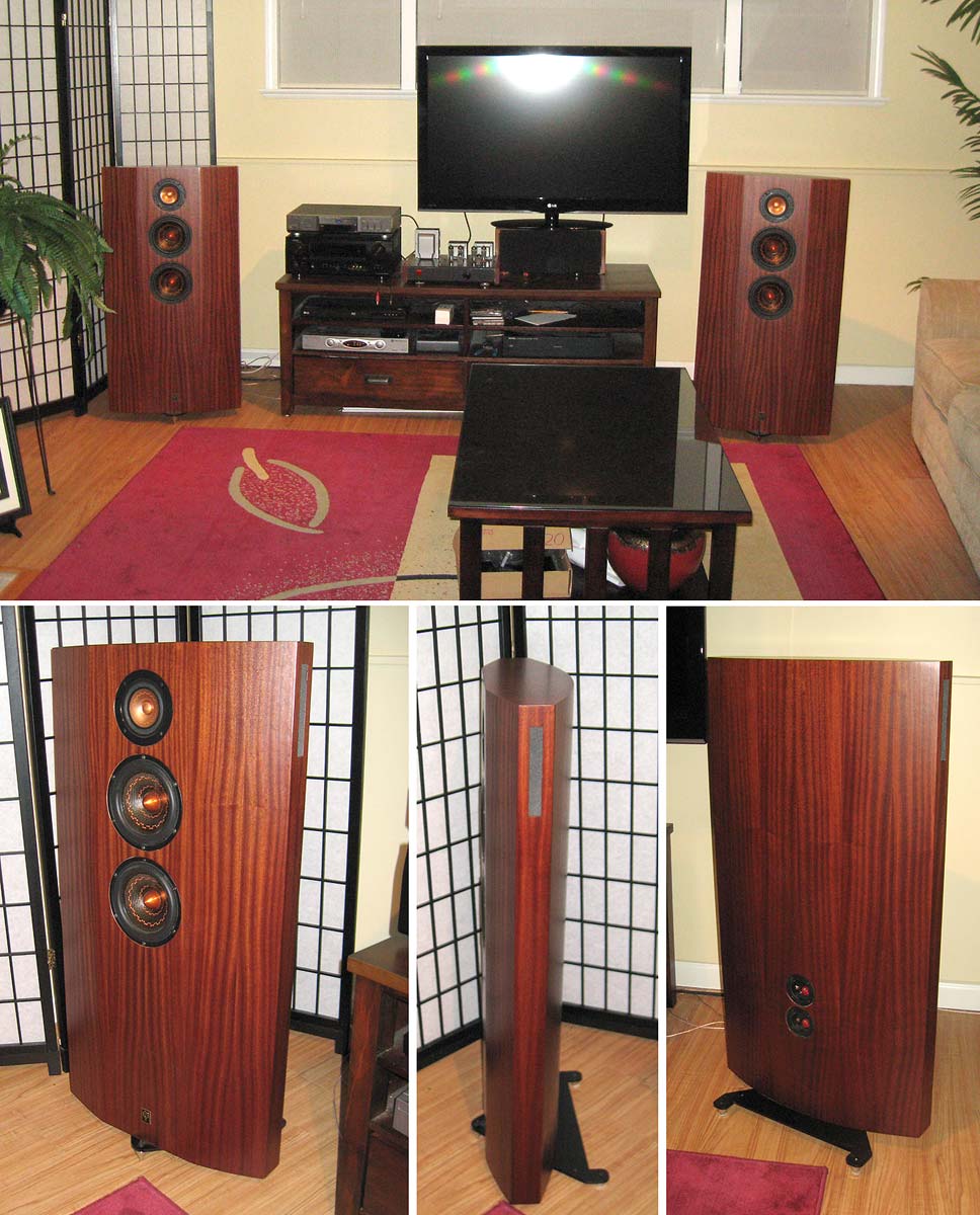
An exampleof a wide loudpseaker that images very well:
dave
dave
FWIW/YMMV, etc., my ROT for point of diminishing returns was 25" wide = 4" round over, the largest I could conveniently saw cut/shape (had no large router back then, so no clue what its safe limit is).At 32" there is no need for a round over
You shared with us the formula to figure out the size roll over per frequency/baffle width interact. I can't find it just yet.FWIW
Don't recall or saved a link, but for the 25" wide = 4" round over I rounded up 25.133" wide:
~13543.8"_sec (~34400 cm_sec)/25.133 = 538.885 Hz
~13543.8/pi/538.885 = 8"
8"/2 = 4" round over
~13543.8"_sec (~34400 cm_sec)/25.133 = 538.885 Hz
~13543.8/pi/538.885 = 8"
8"/2 = 4" round over
It’s not an ‘effect’…..it’s a difference in the point source presentation……and it’s more than obvious once you’ve experienced it in a comparative situation. While our hearing system isn’t SONAR, it’s not terrible by animal kingdom standards either. We just don’t practice those acuity skills in our daily lives enough to appreciate what we do have.Didn't experienced any of these effects, but I used offset driver arrangement on the baffle.
Then it's a phenomenon. Okay I get it what you want to say, but first we need to clear, what is large and what is small baffle in our claims. In my view, up to approx 25 cm is called small baffle.It’s not an ‘effect’
So the baffle can be too large, and the diffraction effects can be perceived as distinct sound sources?
On another forum I read that a Sonus Faber Stradivari sounded horrible in it's fresh new home, the singer had as wide mouth as the distance of the speakers to each other.
Last edited:
I think absolute dimensions do not matter at all. Only relation of transducer size to baffle size matters for the secondary sound source that forms at the edge. 25cm baffle would make problematic edge diffraction back wave for 10cm driver, but for 25cm driver it would be fine.
Absolute dimensions would affect interaction with room, which is independent of edge diffraction problem, because one can have any sized baffle with more or less edge diffraction making secondary sound source. Absolute size will also make audible difference, but is different issue altogether. Absolute dimensions matter overall directivity of a speaker, but also at which frequency bandwidth any diffraction back wave happens which might make it more or less audible, but "amount of diffraction problem" does not depend on absolute dimensions, only relative dimensions.
If baffle is much bigger than transducers, then it could be problematic sounding. When baffle is no bigger than transducers it makes very little problematic secondary sound source, because the sound that emits at the edge is almost the same as the driver sound, only few centimeters late and in midband basically no different than sound emitting from the cone itself. Response narrows due to secondary sound source even with minimal baffle, but this can be utilized to help with overall directivity unlike the ripple that happens if baffle is much bigger than transducer. Baffle could be 50cm, if transducers / waveguides are ~50cm as well, and thats minimal baffle in terms of edge diffraction secondary sound source, as minimal as 25cm baffle with 25cm sound soures, or 10cm wide with 10cm sources on it.
Diffraction is sound going around an object, which is not a problem here as the sound heads away from listening window (through room reflections it might, this is the other problem). Problem with edge diffraction is the backwave that emits at the edge towards listening window right after direct sound. This is basically low passed sound and has location, delay and dimensions and polarity different from the direct sound. The edge becomes additional sound source whose frequency response and delay is different than sound of the drivers, to any direction, but especially issue within listening window.
If this is hard to imagine, try ripple tank, adjust size of the obstacle relative to wavelength, or vise versa, and see what the backwave that emits looks like. Try line source instead of point source and so on. It is good tool to get intuition through visuals.
https://www.falstad.com/ripple/Ripple.html?rol=$+3+512+64+0+0+961+0.048828125 s+2+273+207+2+0.732421875+0+10.001413602849373+99.99941507823934+1+0 b+0+219+211+328+279+0
Attachments

Last edited:
After a quick check I would rewrite the formular as r = l / (2*pi) 🤓 but of course it's important to have the knowlede that this correlates with the wavelength.Don't recall or saved a link, but for the 25" wide = 4" round over I rounded up 25.133" wide:
~13543.8"_sec (~34400 cm_sec)/25.133 = 538.885 Hz
~13543.8/pi/538.885 = 8"
8"/2 = 4" round over
To be honest I have good results already with 30-50% smaller radius but the often used 10mm only work at relatively high frequencies.
Hi,
never heard it playing, but if you want to analyze it's diffraction performance it's possible. Found dimensions that it's 520mm wide, and looks to be about that in height as well, and now one can approximate what the round overs do and what the size does. I'll questimate it is 8" woofer and here is example using ideal transducers, using 50mm diameter for tweeter as it seems to have some waveguide to it. Also quessing 100mm radius for the roundover. Lots of guessing, but this example is to look some relative differences so doesn't matter too much.
This is ideal woofer like in LS1 without any crossover, left image is with the edge roundover and the second without to demonstrate how much the roundover helps, and what the diretivity is due to big baffle.


Same for tweeter, without and with roundover.


Obviously the baffle is made wide to increase directivity well below 1kHz and roundovers are to help with the edge diffraction, especially for the tweeter. What roundovers do they remove the edge for short wavelengths keeping the bulk the same for low wavelengths.
If the radius was even bigger, there would be even less secondary sound from the edge. (this would mean the box would be deeper which would again change things. Depth is not included in these simple diffractions sims, only front edge).


ps. it takes longer to compose a post like this than roll lots of simulations with the VituixCAD diffraction tool using ideal transducer and baffle. It really is great tool to get intuition with this stuff, as it's real time allowing very quick tests that help reasoning. I recommend everyone to play with it when ever there is unknowns regarding this stuff. Being simplified and ideal it shows the underlying phenomenon without all the details of reality blurring the big picture 🙂
Last edited:
If you like @tmuikku 's graphs, I have a started a small directivity study with real drivers on real cabinets, over at:
https://www.htguide.com/forum/forum...ivity-ribbons-domes-wg-horns-baffled-or-naked
https://www.htguide.com/forum/forum...ivity-ribbons-domes-wg-horns-baffled-or-naked
How do you generate an ideal driver in VituixCAD?
The sim shows that first baffle step dips start at 1kHz for such a wide baffle. If you care about these you need LARGE roundovers. There are also ripples at higher frequencies - you can do smaller roundovers for these.
The sim shows that first baffle step dips start at 1kHz for such a wide baffle. If you care about these you need LARGE roundovers. There are also ripples at higher frequencies - you can do smaller roundovers for these.
tktran, yeah thanks, I've had my share and can generalize with imagination and use simulation to test 😀
by not loading any driver data 🙂 in diffraction tool just input baffle and driver size and hit "new" and thats it. If you want to look at full polars, then you need to "measure", iow check "feed driver" and hit export. This will send data to driver that is selected in the main progam, and you can now inspect the sixpack, impulse response and so on.How do you generate an ideal driver in VituixCAD?
The sim shows that first baffle step dips start at 1kHz for such a wide baffle. If you care about these you need LARGE roundovers. There are also ripples at higher frequencies - you can do smaller roundovers for these.
It is usefull to think the diffraction tool similar to your real measurement setup, the data it generates is similar to what you'd get if you follow vituixcad measurement instructions. I say similar, because the diffraction model is relatively simple, and it's all virtual so no need for gating or nearfield measurments or anything like semianechoic real measurements would need. It's similar in a way, that you'd use both diffraction sim data and real measured data similarly in the main program. Sims are nice for playing around.
ps.
For succesfully navigating through a speaker acoustic design of course the structure affects all the directivity of overall system, how the crossover region works out as total, and what the edge diffraction backwave is, not just any single one of these but of course everything needs to work nicely. Search for kimmosto posts for lots of insight how to juggle with it. Unlike common "myth" it's not useful to have exactly same directivity at crossover for both transducers, smoother DI available if tweeter directivity collapses while woofer's is boosted, hence particular transducers and baffle shape managing all of this, iow. the structure he often uses makes fine system for what he is looking for and it's good stuff try to understand why in order to be jugle your own system.
Last edited:
and modelling an ideal driver is limited.How do you generate an ideal driver in VituixCAD?
There are two "woofer" versions of LS1: one with a Seas 8 inch Excel woofer, which is said to work "pistonic" up to the crossover frequency, and a cheaper one with a (when I am right) carbon fibre woofer which will not work pistonic but will break up before crossover. How to model that??
Using real measured data, or very complicated FEM/BEM simulation stuff.
But it's not even necessary at planning phase: you can assume any driver breaks up at some point, about when wavelength is something like cone diameter, most bit higher, some lower, but in general you could assume to avoid going that high with any particular driver due to many reasons, breakups, modes inside the box, edge diffraction, beaming for example. If you arrive with a speaker system that requires particular sized driver whose pass band must be clean to some relatively short wavelength (high in frequency), only then you must go after special expensive drivers that full fills the task, buy suitable driver! Until then you can use ideal drivers to come up with a concept that would work for application and goal you have set for your system. Buying drivers is about last phase of making a speaker system, just before measuring, after the design is done basically. Well, assuming there is enough knowledge of real drivers and systems to be able to come up with a realistic system, a system that can be built physically as well as suitable drivers are actually available.
ps. Staying on the topic, thinking stuff with wavelength shows about 90% of all speaker and home playback problems / issues would fall on midrange, just because midrange frequencies (wavelength) are about size of our speaker boxes, our selves, drivers available, early reflection path lengths in small room, panel resonances, crossovers and so on. All kinds of resonances, secondary sound sources as well as auditory system specialities happen in midrange like localization, masking, ITD/ILD, all kinds of stuff. I would bet an euphoric midrange tackless whole bunch of issues considering loudspeakers and home playback situation, basically most issues need to be tackled, there isn't just one magic bullet that would do everything. If you find it for one room and practical positioning, it doesn't necessarily mean it's optimal for another.
Last edited:
- Home
- Loudspeakers
- Multi-Way
- Most euphoric high-end midrange you have heard?