But then maybe the high voltage rating has something to do with the sound?
No, it doesn't.
If I can still get the 1837, perhaps best to stick with it then for best sound, even at 50mA bias.
Mouser still has over 3,700 Toshiba '1837s in stock. Xrk971, you better grab them while you can!
If you're pleased with the Toshibas, why waste your time using an inferior, high voltage device like the 2SA1381 designed for CRT displays??
They're alright for higher voltage VAS in power amps, but pretty much suck for lower voltage applications such as HA and line stages.
Been there and done that along with their complementary 2SC3503.
Perhaps ole' Hugh(or dude as he referred to me as) can prove me wrong.

X,
I may have a couple of the Tosh devices - I will send to you.
Ammel,
No disagree at all - you are right. In truth I regret the low appelation; it seems you are not a dude at all....
HD
I may have a couple of the Tosh devices - I will send to you.
Ammel,
No disagree at all - you are right. In truth I regret the low appelation; it seems you are not a dude at all....
HD
But then maybe the high voltage rating has something to do with the sound?
yes the bigger the better !
Perhaps ole' Hugh(or dude as he referred to me as) can prove me wrong.
it seems you are not a dude at all....
HD
Maybe cool 'n crazy audio dudes...!

Ok partypooper we got the message already, now retract back to your PSU thread and play that clueless poofter in dire need for some trivial PCB designing advices.
And to X and Hugh I want to say thank you for all your input in this thread, it has been an interesting walk in following the evolutionary dissection and development of this simple and beautiful HA. Recently I have been quite quiet in this thread partly due to various reasons over here putting a break on some things, but being past one hurdle I am soon going to order some of the components needed for this sweet little HA which is also very much needed when using my computer for not only music listening during late nights but also radio shows, internet videos etc..
I set my headamps all out in a row on the bench so I could compare the sound by switching headphone jacks. It was mainly to test the new 2SA1837 amp against the two big gorillas: the DCG3 (currently top), the big mosfet source follower from post 1, and a new commercial offering of a state of the art Muses02/LME49600 based Fiio A5. It was late so testing still underway. To be continued ...
I set my headamps all out in a row on the bench so I could compare the sound by switching headphone jacks. It was mainly to test the new 2SA1837 amp against the two big gorillas: the DCG3 (currently top), the big mosfet source follower from post 1, and a new commercial offering of a state of the art Muses02/LME49600 based Fiio A5. It was late so testing still underway. To be continued ...
You are missing one in that list, GW mk3.😀
Hi Dadod,
I have been wanting to build your GW Mk3 but took a while to acquire all the different actives needed. I need to match the BC550/560's now. Some need Hfe match and some need Vce matching. Then I can begin stuffing the parts and then solder the ~60 odd transistors - you can see why I like 2 transistor amps. 🙂
I have been wanting to build your GW Mk3 but took a while to acquire all the different actives needed. I need to match the BC550/560's now. Some need Hfe match and some need Vce matching. Then I can begin stuffing the parts and then solder the ~60 odd transistors - you can see why I like 2 transistor amps. 🙂
Hi Dadod,
I have been wanting to build your GW Mk3 but took a while to acquire all the different actives needed. I need to match the BC550/560's now. Some need Hfe match and some need Vce matching. Then I can begin stuffing the parts and then solder the ~60 odd transistors - you can see why I like 2 transistor amps. 🙂
I know, simple is easy, but where is challenge in that, and where did you find the ~60 odd transistors, nothing odd in them.😱 😕
xrk,
Can you post the schematic with the desktop version as built?
I have few queries regarding the components. May be you have answered some of them earlier in the thread.
1. R8 (220) and R9 (100) when passing 135mA will dissipate lot of heat. I see for 220 ohms, dissipation is around 4W? Is this correct or the value of these are different in the built circuit?
2. The coupling capacitor value of 47uF and Rload of 250 ohms is good for enough for headphones with 50 ohm impedance?
Thanks
xrk,
Can you post the schematic with the desktop version as built?
I have few queries regarding the components. May be you have answered some of them earlier in the thread.
1. R8 (220) and R9 (100) when passing 135mA will dissipate lot of heat. I see for 220 ohms, dissipation is around 4W? Is this correct or the value of these are different in the built circuit?
2. The coupling capacitor value of 47uF and Rload of 250 ohms is good for enough for headphones with 50 ohm impedance?
Thanks
Are you referring to the BF862-BD140 amp or the BF862-2SA1837 desktop amp?
Hello xrk,
I was referring to BF862-2SA1837 desktop amp. I was looking at the schematic posted for BF862-BD140 and assumed you swapped BD140 to 1837 but was not sure if other components were shifted.
Thanks
Are you referring to the BF862-BD140 amp or the BF862-2SA1837 desktop amp?
I was referring to BF862-2SA1837 desktop amp. I was looking at the schematic posted for BF862-BD140 and assumed you swapped BD140 to 1837 but was not sure if other components were shifted.
Thanks
Hello xrk,
I was referring to BF862-2SA1837 desktop amp. I was looking at the schematic posted for BF862-BD140 and assumed you swapped BD140 to 1837 but was not sure if other components were shifted.
Thanks
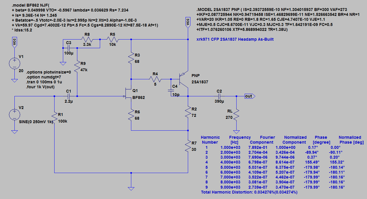
Oh it's quite different. Here is the schematic as-built. You need a bigger output cap depending on how low the impedance is. The fc is calculated using the relation 1/(2 x pi x R x C) where R is the headphone impedance. A 470uF cap should give about 11Hz fc.
The Complementary Feedback Pair (CFP) amp topology using the 2SA1837 indeed provides a very nice result. The settings were provided to me by Aksa and I modified them slightly to take advantage of parallel resistors (5 x 360R gives 72R and 4 x 120R gives 30R) for higher dissipation powers.
Here is the as-built schematic. Note that you need to provide a very low ripple power supply as the amp itself has hardly any CMRR. A cap multiplier is highly recommended.
Attachments
New thread for listening to all my headamps
http://www.diyaudio.com/forums/soli...al-audition-several-headamps.html#post4977888
http://www.diyaudio.com/forums/soli...al-audition-several-headamps.html#post4977888
Is it possible to measure HD that is lower than the theoretically predicted value from the sim? I supposed so, because that is what is happening on the CFP 2SA1837 amp.
I am now getting measured THD of 0.0056% at 700mV output into 270R. Usually, the measurement is worse than sim. Burn-in may have something to do with it - I left it on playing music for 24 hrs straight.
I am now getting measured THD of 0.0056% at 700mV output into 270R. Usually, the measurement is worse than sim. Burn-in may have something to do with it - I left it on playing music for 24 hrs straight.
Last edited:
Find out how you can get a free Pocket Class A Headamp here:
http://www.diyaudio.com/forums/head...-audition-several-headamps-5.html#post4981007
http://www.diyaudio.com/forums/head...-audition-several-headamps-5.html#post4981007
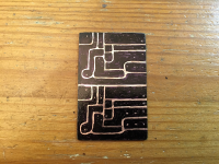
Xrk this will be inderesting if someone can redraw this into a clear pdf for home etching.
Attachments
Last edited:
You could just use that image aas basis for Paint or some other graphics program as is - just scale it to fit the pin spacing of parts.
- Home
- Amplifiers
- Headphone Systems
- MOSFET Source Follower Headamp