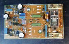
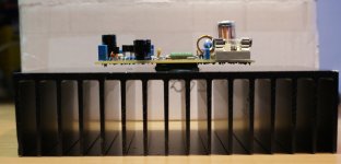
Many mosfet power amplifiers based on 2SJ162/2SK1058 lateral mosfets are made. This one is particularly suitable for home-use, being small, having moderate power with very low distortion:
More info:
Mosfet Power Amplifier
- Max output power: 100W@8ohm, 150W@4ohm
- THD+N (1kHz): < 0.005% (measured!)
- PCB dimensions: 100x60mm
- Input sensitivity: 1.2V rms
- Input impedance: 22kohm
- Bandwidth: 80kHz
- Voltage gain: 27dB
More info:
Mosfet Power Amplifier
Attachments
There appeared to be a ground loop in the measurement setup, so I removed it and repeated the measurements. THD and noise characteristics were even better, with measured A-weighted THD+N @ 1kHz using 8 ohm load 0.0021%!
Mosfet Amplifier
Hi, I am interested in buying kits for this amplifier. Please let me know if they are available and what the price is. I will be using it with a 100V line output transformer and a six channel mixer for our church.
Regards
Herman
hermanb3@absamail.co.za
Hi, I am interested in buying kits for this amplifier. Please let me know if they are available and what the price is. I will be using it with a 100V line output transformer and a six channel mixer for our church.
Regards
Herman
hermanb3@absamail.co.za
Many mosfet power amplifiers based on 2SJ162/2SK1058 lateral mosfets are made. This one is particularly suitable for home-use, being small, having moderate power with very low distortion:
Available as complete kit or pcb-only, so you can select components yourself. Mosfets/components are also available separately.
- Max output power: 100W@8ohm, 150W@4ohm
- THD+N (1kHz): < 0.005% (measured!)
- PCB dimensions: 100x60mm
- Input sensitivity: 1.2V rms
- Input impedance: 22kohm
- Bandwidth: 80kHz
- Voltage gain: 27dB
More info:
Mosfet Power Amplifier
Hi Herman, kits are in stock: 50 euro for a single kit (pcb+components), decreases to 40 euro/kit if you buy 5 or more.
Menno
Menno

Assuming one channel, 100W @ 8 ohm, you need about 48V rail voltage, which is also perfect for the output relay. Minimum transformer VA of 125VA would then be required.What is the recommended rail voltage ? And the transformer VA ?
150VA are commonly available, and 35-0-35 transformer will give you 48V rail, which is about ideal.
More info, including transformer computations for other cases: Mosfet Power Amplifier
Assuming one channel, 100W @ 8 ohm, you need about 48V rail voltage, which is also perfect for the output relay. Minimum transformer VA of 125VA would then be required.
150VA are commonly available, and 35-0-35 transformer will give you 48V rail, which is about ideal.
More info, including transformer computations for other cases: Mosfet Power Amplifier
Hi djuke!

Where is the PCB and part list?
Otherwise the amplifier is very good!😉🙂
thenks and cheers !
PCB's can be bought in my webshop. When you buy a pcb or kit, you will receive the part list with all suggested values with it.
Many mosfet power amplifiers based on 2SJ162/2SK1058 lateral mosfets are made. This one is particularly suitable for home-use, being small, having moderate power with very low distortion:
Available as complete kit or pcb-only, so you can select components yourself. Mosfets/components are also available separately.
- Max output power: 100W@8ohm, 150W@4ohm
- THD+N (1kHz): < 0.005% (measured!)
- PCB dimensions: 100x60mm
- Input sensitivity: 1.2V rms
- Input impedance: 22kohm
- Bandwidth: 80kHz
- Voltage gain: 27dB
More info:
Mosfet Power Amplifier
I calculated the audio amplifier.
With these values of the components to shematics ate amplifier works well or these values are only theoretical?😕
thank you and cheers!

Last edited:
Great work, I actually use different components and values in the input and VA stage, but using 2N5551/2N5401 is certainly an option.I calculated the audio amplifier.
Please keep me informed when the amp has actually been built and measured with these component values.
Audio amplifier which I calculated above will work quite well. Of course you can improve audio amplifier diagram, but I think that is pointless.
Hi donpetru!
What changes are needed to make the shematic for the output transistors to be placed a few mosfet IRFP240/IRFP9240 or bipolar pair MJL4281A/MJL4302A?
thank you!
What changes are needed to make the shematic for the output transistors to be placed a few mosfet IRFP240/IRFP9240 or bipolar pair MJL4281A/MJL4302A?
thank you!
Simulation of my amplifier
Hello Donpetru!
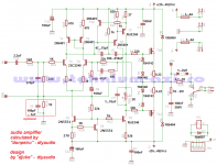
Since I see that you have a progam for the simulation of electronics circuits, so please if you are able to create a simulation of my audio amplifier, which I designed for this shematic (Figure 1F).
Big thanks in advance!
Hello Donpetru!
Since I see that you have a progam for the simulation of electronics circuits, so please if you are able to create a simulation of my audio amplifier, which I designed for this shematic (Figure 1F).
Big thanks in advance!
Attachments
formula 22,
That diagram audio amplifier seems not optimized. For example, there is no point can mount only trim P1 in the input circuit of the audio amplifier. Right is to mount a resistor in series with the trim P1. But so, not 100% good. It's much better to try to let the resistance instead of P1, but that only after having established experimental optimum value of current in the input circuit. Bootstrap capacitor C8 is no current solution. It's old-fashioned, as is diagram audio amplifier. Then, R2 and R9 are too high.
Finally, if you want one audio amplifier diagram worth done, download and analyze all schematics (pdf files) that were posted in this topic or thread:
KIT 0205 - schema, modernizare, constructie amplificator - Comunitatea Tehnium Azi
Nice day.
- Status
- Not open for further replies.
- Home
- Vendor's Bazaar
- Mosfet power amplifier 2SJ162/2SK1058