I understand.
I followed your experiments for 10 years. Especially the recent ones where you started experimenting with solid state devices. Those inspired me to look at vacuum tube solid state hybrid technologies.
I built Michael Koster's Schadeode. I was impressed with the results. A 4D32 produced 1 watt at 0.08% midband distortion.
Then I put the LND150 split load phase inverter in front of it and got the same result.
Later this year I will mock up a push pull version with the LND150 PI for the input.
Steve
Andy,
You might be interested in reversing the order and making a williamson style amp.
I experimented with an LND150 split load phase inverter for the input driving a small signal dual triode.
Excellent balance and the distortion from the LND150 was at the residual of my HP8903 analyzer.
Steve
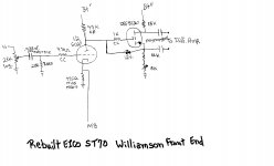
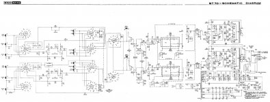
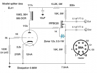
Somebody said Williamson. 😀 I worked with Mike Samra on an EICO ST70 carcass. We replaced the power trafo, kept the O/P "iron", and switched to Williamson topology in the power section, with Russian 6Π3C-E (6p3s-e) "finals". The available socket count forced us to use a MOSFET as the "concertina" phase splitter. Ask Samra what it sounds like.
BTW, we did "borrow" a few bits from the Heath W5-M. 😉
Attachments

Eli - your hand drawn schematic is perfect for my needs. But could you post it again with all the voltages included? I'm shooting for a B+ of 300v and I need to know what voltage to have on the anode of the first stage if it's direct coupled. All the other voltages would help too.
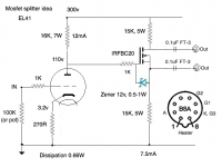
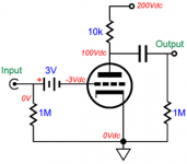
As I posted earlier, try 100-125V at anode of first stage (V1), roughly about 1/3 of B+. You'll have slightly less than 50Vp (100Vpp) max. swing with 100v at V1 plate to ~< 25Vp (50Vpp) max. swing with 125v at V1 plate.I need to know what voltage to have on the anode of the first stage if it's direct coupled.
I'm shooting for a B+ of 300v and I need to know what voltage to have on the anode of the first stage if it's direct coupled.
The splitter has a gain of two, so needs to swing twice the output voltage of the first stage. If both were ideal, the second stage would idle at half the supply voltage across itself and half across its two load resistors, half (of half) each. This would put the anode of the first stage at 1/4 of supply voltage.
But real valves aren't ideal, although the MOSFETs are close enough for baseball, and the first anode ends up at about 1/3 to 1/4 supply voltage and closer to 1/3, as indra1 has said.
YOS,
Chris
I have some IRFBC20 coming, so will be able to test this out. Thanks for the help.
Is there any problem with using a plate choke as load for the input tube?
Is there any problem with using a plate choke as load for the input tube?
Not enough headroom for mosfet drain swing.Is there any problem with using a plate choke as load for the input tube?
Not enough headroom for mosfet drain swing.
Could you expand on this please? I have very little working knowledge of solid state devices. What's different between a plate choke and a resistor loading? The mosfet can stay at 300v B+, and a dropper resistor + cap can be used in the B+ feed to the plate choke. The anode of the input tube can stay at 100-125v as you recommend.
Is there any problem with using a plate choke as load for the input tube?
Well, think about it this way: how much of the supply DC voltage will drop across that choke? That amount of voltage will be subtracted from the supply voltage to determine the first stage's anode DC voltage. Then, this anode voltage *is* the splitter's grid voltage. At what DC conditions would the splitter operate?
Ohm's Law is always the essential first step in answering questions. Except for questions about women or religion, for which there are no answers.
YOS,
Chris
Should be ok in this particular case. We need roughly 1/3 B+ at mosfet splitter drain resistor, source resistor and Vds (drain to source voltage), the dropper resistor maintain needed headroom. You can try, the choke and cap will give a different presentation but I do not expect any sonic benefit.Could you expand on this please? I have very little working knowledge of solid state devices. What's different between a plate choke and a resistor loading? The mosfet can stay at 300v B+, and a dropper resistor + cap can be used in the B+ feed to the plate choke. The anode of the input tube can stay at 100-125v as you recommend.
Another possibility is a simple ccs. Single bjt, LED, and emitter pot for tweaking. I have built several.
Here's a specimen first stage with resistor and plate choke. So why exactly doesn't the plate choke work? Trying to understand this....
You're still wasting just as much power in resistors, but now you need to spend extra money on a choke and the chassis real estate to fit it... Pourquoi?
You're still wasting just as much power in resistors, but now you need to spend extra money on a choke and the chassis real estate to fit it... Pourquoi?
Good question....
- I have an existing amp where space is very tight. This will use a resistor load because there's no space for a plate choke or CCS.
- I have another PP amp project where I have much more space available.
I prefer a plate choke because not only does it sound better, but it also allows me to put more current through the tube. This means I can use a smaller cathode resistor and i don't have to use a cathode bypass cap if there's enough inductance in the plate choke. The ones I use have inductances of around 150H.
With a B+ of 300v and an anode voltage of 110v, you have a drop of 190v. If you put say 10mA through the tube you get an anode resistor of 19K. If you use a tube with a Ri of 2 or under and the bias voltage is 1.5v you have a cathode resistor of 150R which may sound OK unbypassed. Bias voltage of 2v and the cap is 200R etc. One of my goals is always to avoid cathode bypass caps where possible. So I do a bit of juggling with tubes and operating points.
Fair enough.
Another alternative to bypass caps would be diode bias on the cathode or battery bias on the grid. If you arrange the battery bias right, and use a carbon zinc battery,. it'll provide a stable bias voltage for 50+ years 🙂
Another alternative to bypass caps would be diode bias on the cathode or battery bias on the grid. If you arrange the battery bias right, and use a carbon zinc battery,. it'll provide a stable bias voltage for 50+ years 🙂
Attachments
I've tried battery bias and SIC diode bias and I prefer a plain resistor of small value. Sounds smoother to me. I don't like any edge to the sound. With DHTs I use filament bias where I can.
Where a cathode bypass is required, on output tubes like 300b, I use good polypropylene caps. I'm about to try out some DC Link caps, in fact.
Where a cathode bypass is required, on output tubes like 300b, I use good polypropylene caps. I'm about to try out some DC Link caps, in fact.
I bypass the cathode on the first stage of my designs with 1000uF Aluminum polymer solid caps. Another member tested it and claims you can reduce THD by 1% by replacing the 330R||1000uF with a red LED.
Off topic, but since we're on the subject of bypass caps here's a brief shootout I just did on the cathodes of my 300b outputs. In order of preference:
- Vishay DC Link Cap, 40uF, 900v
- ICW SA Clarity Cap, polypropylene, 47uF, 630v
- RS electrolytic 100uF, 450v
- ICW PW polypropylene cap, 40uF, 160v
- Aerovox motor run cap, polypropylene, 40uF, 450v
The DC Link caps were a clear improvement on all the others - audibly more detail and better timbre to voices and instruments and a generally more involving sound. The two ICW caps were similar - smooth but flat and quite veiled in sound, rather boring in fact. The bigger Clarity Cap (it's very big in fact) was a little better but still rather flat. The RS electrolytic surprised me - it wasn't as smooth as the Clarity Cap but it had more life and was arguably more involving though a little coarser. This is just a generic old cap with many years on it. The motor run cap was flat and boring and a little coarser than the ICW caps but otherwise fairly similar to the PW cap.
Conclusion - get some DC Link caps! The sound improved quite noticeably. I'll be ripping out all my ICW caps, which have a good reputation and are sold as "audio" caps. I won't be doing a shootout of electrolytics, but I imagine there's room for improvement there. They were better than I expected, though outclassed by the DC Links.
- Home
- Amplifiers
- Tubes / Valves
- MosFET or other semiconductor substitute for cathodyne?