Any body tested this amp in the application of rugged use PA?
How was the sonics the treble mid and bass ???
How was the sonics the treble mid and bass ???
Last edited:
NE555 protection circuit is working only if i remove 1uf capacitor other wise its continuously switching.......and not stopping until i remove capacitor what could be the reason??
it is switching on/off/ on/off/ or it is just switched off? is it connected to any device or...?
it is switching on/off/ on/off/ or it is just switched off? is it connected to any device or...?
on/off on/off......
no didn't connect any device
No reply
Finally I have removed 1uF capacitor
what is the maximum voltage that i can give to this NE555 protection
Finally I have removed 1uF capacitor
what is the maximum voltage that i can give to this NE555 protection
No reply
Finally I have removed 1uF capacitor
what is the maximum voltage that i can give to this NE555 protection
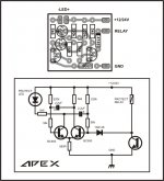
Do you connect 10k NTC for thermal protect or 10k resistor instead NTC, 1uF capacitor is for turn on delay do not remove but use 4,7uF to increase time to 5 sec.
Do you connect 10k NTC for thermal protect or 10k resistor instead NTC, 1uF capacitor is for turn on delay do not remove but use 4,7uF to increase time to 5 sec.
Yes i have used 10k NTC when i insert 1uF capacitor the relay is switching on/off/on/off......when i remove its stopping and working fine with DC protect and thermal protect except turn on delay
hi comasus,
can u tell me how u check dc protect and thermal protect working or not, i already checked. but how u did?
what is the relay delay time when on and off.
can u post some images top and bottom pcb
can u tell me how u check dc protect and thermal protect working or not, i already checked. but how u did?
what is the relay delay time when on and off.
can u post some images top and bottom pcb
hi comasus,
can u tell me how u check dc protect and thermal protect working or not, i already checked. but how u did?
what is the relay delay time when on and off.
can u post some images top and bottom pcb
I have checked it by giving 2vdc by DMM
and used solder for ntc
turn on delay is not working
i have inserted in the speaker box with the amplifier so for the images i have to remove the cover again
expect turn on delay remaining is perfect so i have kept it inside confidently
how u make the pcb? toner transfer method or silkscreen. which layout u followed.
u said turn on delay is not working. then why u put inside the speaker box, can u share some images. top and bottom pcb.
u said turn on delay is not working. then why u put inside the speaker box, can u share some images. top and bottom pcb.
Last edited:
how u make the pcb? toner transfer method or silkscreen. which layout u followed.
u said turn on delay is not working. then why u put inside the speaker box, can u share some images. top and bottom pcb.
Toner transfer
Followed attached image
I posted my problem but no help and compromised having dc protect
I put inside the speaker as the amplifier was fitted in it
Attachments
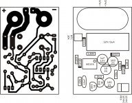
can u share some images. top and bottom pcb.
It will take some time
Simple Full Complementary Simetry +/-80V. Voltage amplifier/driver biased with 30mA. This driver circuit stabilized BIAS in output stage. Exelent stability without oscilation, hum and noise, sound great.
RMS Power: 240W 8ohm, 350W 4ohm
thanks for sharing projects 😀
this a great 😉
MOSFET amplification 😱
hello,i have an problem.i use microcontroller to switch mosfet(IRF840) in boost converter but when i connect the microcontroller its output decreasing thats why it cannot switch this mosfet.so how can i remove this loading problem,plzIf you had used Lateral Mosfets in the output stage then i guess you could get away with such a simple biasing scheme. Lateral Mosfets have a negative temperature coefficient so they'll tend to reduce quiescent current as they heat up.
IRFP240 & it's complement have a positive temp coefficient (until they are drawing many Amps of current) so they'll conduct more current as they heat up. There is no allowance for this in your circuit diagram, you'd need something similar to what is used in a transistorised output stage.
I might be wrong, but i don't think so 😉
hello,i have an problem that to switch mosfet(IRF840) in boost converter by microcontroller .when i connect the microcontroller to mosfet thats the output of the microcontroller out put goes to 5v to 2.5 v(apporiximately) due to loading effect.how can i remove this loading problem.plz anyone
- Home
- Amplifiers
- Solid State
- MOSFET Amplifier IRFP240/IRFP9240