sorry i thought i would double check, pin 5 is 0.9volt, pin 6 is 1.8 volt. Unsure why i got dodgy reading before probably didnt have good contact
with max volume on source i have pin 5 1.1v pin 6 2v however i just rechecked 5 and 6 on pcb2 and i now also have the same voltage as pcb4.....................
Are you saying that the input (from the RCA jacks) is equal but the output to PCB2 is a 2:1 difference?
Do you have any ChipQuik or other low-temperature alloy?
Do you have any ChipQuik or other low-temperature alloy?
Yes. Low temperature solder alloy.
Have you ever desoldered anything like the 12 pin headers? Chipquik makes it easy. Without it, it may be a battle and the main board may be damaged.
Have you ever desoldered anything like the 12 pin headers? Chipquik makes it easy. Without it, it may be a battle and the main board may be damaged.
I don't want you to risk damaging the board.
Check the output terminals of the op-amp on the RCA board. Are the voltages the same on pins 1 and 7?
Check the output terminals of the op-amp on the RCA board. Are the voltages the same on pins 1 and 7?
ok the only component on the rca board that looks like an op amp is IC1, but it is listed in the manual as a 1.5A Positive Voltage Regulator.
Unsure of pin numbers, from top left to right, pin 4 has 1v, from bottom left to right pin 3 has 0.5v. All others have millivolts.
Unsure of pin numbers, from top left to right, pin 4 has 1v, from bottom left to right pin 3 has 0.5v. All others have millivolts.
Attachments
There is no information on anything but the main board. IC1 on the main board is a regulator.
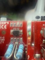
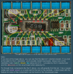
Look at the NE5532 datasheet.
The line marks the pin 1/8 end. The cutout in the silkscreen is another indicator for this board. Also see the marks in the other image.
Look at the NE5532 datasheet.
The line marks the pin 1/8 end. The cutout in the silkscreen is another indicator for this board. Also see the marks in the other image.
Attachments
- Home
- General Interest
- Car Audio
- Mosconi amp fault