For illustrating this (remembering), in post #828, figure 10, I made a "low regime" triode mode graph, with a 6AS7 sort-of results or worst. So the PL509 belongs to this power law miasmatch 😡🙂 (far, far away from tubes like "the Hell"). Unfortunately I don't saved the resulting gm but when I play againg with this I will measure this.... UL and triode modded (higher gm) pentodes have considerable "roll-over" in their triode plate curves due to the power law mis-match. .....
..
The gm graph (versus drive V) is the 1st derivative of the power law formula.
So for Square law: Ip = k(Vg)^2 one gets gm = dIp/dVg = 2k(Vg)^1 or just 2kVg
So a linear ramping gm graph indicates a square law Ip rule.
Of course, a linear ramping Ip versus Vg directly indicates a 1st power law: Ip = kVg ,and the gm = dI/dVg = k or a constant gm.
A 3/2 power law: Ip = k(Vg)^1.5 yields a Sqrt gm function: dIp/dVg = 1.5k(Vg)^0.5 That gives a gm graph something like post # 845
Some tube datasheets offer a gm curve set. Not typically output tube ones unfortunately.
E55L for example: https://frank.pocnet.net/sheets/009/e/E55L.pdf
It offers gm versus Vg on page 5, and also gm versus Ip on top of page 9.
(one can combine the Ip and gm formulas to get gm versus Ip, typically more like Sqrt functions ) The flat ramping section of the graph on page 5 indicates square law operation in that region.
..
Since I have a Aikido used as a DAC output, with E88CC, I can share some results: I measured this when I build it. At ~2Vrms output, THD is 0.008% at 3k9 load! Challenges most PC card inputs. Hmmm... too good to be true? Maybe, since the 3k9 load provides a additional HD cancelling. But even with other loads, HD is very low for such a simple circuit (like <0.03% maximum).........
I would love to find a means to fix the power law tracking for trioded pentodes and UL mode, but I haven't seen anything yet, except the equally non-linear load scheme used in the Aikido gain stage.
.......
..
But I fell compelled to test again something. Some years ago, when I started to use PC FFT, I needed to have a linear high-voltage stage for feeding a PL509 G2 in a plasma tweeter. Is needed something like 60Vpk at least. I assembled a famous SRPP, wired as John Broskie indicated for HD cancelling (with things like not decoupling the lower cathode resistor etc.). And simulated a ideal load: 47k for a 3k3 cathode resistor. +B in the 250V ballpark. If memory serves now, I obtained 130Vrms with scary low THD for such high voltage, with excellent HD distribution. Loadline cancellation, power law cancellation ...or...? This is a test I need to repeat to see if I imagined things 🙄😛😀😉🙂
Would there be any virtue in cascading two mosfet followers, perhaps a p-follower into an n-follower? Would this be a good way to apply the crazy drive feedback?
I assume you are meaning to use such a scheme for plate (or UL tap) to driver N Fdbk of some form.
Anything coming from the plate does have the issue of being referenced to B+, as far as actual output signal goes (so very poor PSRR). So if one gate is driven by a resistive divider from the plate, and the second gate is AC referenced to B+ (N and P channel Sources connected), that could remove the PSRR issue. But it does put two naked Mosfet gate V to I transfer functions into the critical N Fdbk loop. This is not going to set well with purists.
I think one would want to keep the mode of Mosfet(s) operation as a current in, to current out, transfer (unity transfer function). For that, only one P type Mosfet would be needed. A (Schade like) resistor from the plate to the P Mosfet Source terminal (possibly a divider R setup to B+, as seen below), and the gate AC referenced to B+. (the Gate, DC only, referenced to some convenient +V) That removes the B+ noise influence then, and allows Drain current coupling to the driver stage. (so still B+ voltage insensitive) The Mosfet Drain would then couple to the driver plate. (similar to the Wavebourne diagram below, except driver tube plate connected to the Mosfet Drain instead. With two current sources connected together at the output tube grid, some impedance lowering R is needed, or use a triode driver, or a servo for DC bias control.)
One could flip this around to use an N Mosfet, with gate AC referenced to B+, the Schade R to a Source divider R.
Then, Wavebourne has a Schade /Mosfet scheme using a P channel Mosfet, see below. It does put one Mosfet gate V to I function in the N Fdbk and forward signal path. (essentially, the P Mosfet becomes the driver stage here)
..
Attachments
Last edited:
Thank you smoking-amp; that has certainly given me a lot to think about. I have followed your "crazy-drive" posts with utter fascination. In the UK, we don't have the kind of sweep tubes which seem to work best with this scheme-the only common one is EL36/6CM5 (which I think probably would be suitable for lowish power); the Russian ones are easy to get but the one you tested, 6P41S, didn't seem to my eyes to be particularly suitable. Is this simply a matter of the grid exponents?
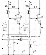
Here is a better description of what I had in mind. No doubt some improvements could be found for DC biasing. This would preserve unity current gain through the Mosfet(s), so should be more acceptable to purists. And the loop gain could be programmable via a loading resistor on the drain/driver_plate. (mainly for pentode drivers) Also showing Twin/Crazy drive of the output tubes too (just Rg2g1 and Rg1k).
6P41S I guess was similar to the 13GB5 tubes. Probably use-able. 21HB5 is quite similar to 13GB5, works good for Crazy/Twin. (see below)
Can always just order some 6HJ5, 6CB5, 6EX6, 26DQ5 or 21LG6 for $4 or so. Maybe shipping is not low cost?
..
6P41S I guess was similar to the 13GB5 tubes. Probably use-able. 21HB5 is quite similar to 13GB5, works good for Crazy/Twin. (see below)
Can always just order some 6HJ5, 6CB5, 6EX6, 26DQ5 or 21LG6 for $4 or so. Maybe shipping is not low cost?
..
Attachments
Last edited:
That's super helpful!
It's the combination of high shipping costs, fixed customs clearance fees on top of the duty and the low Pound to Dollar rate at the moment which makes buying small quantities from the United States rather punitive just now.
It's the combination of high shipping costs, fixed customs clearance fees on top of the duty and the low Pound to Dollar rate at the moment which makes buying small quantities from the United States rather punitive just now.
smoking-amp, now that I think I understand the circuit details a couple more questions:
are triodes really capable of driving the grids with low distortion?
the cathode and Rg1k connect to a relatively low voltage negative supply? does this supply need to be variable?
21HB5 is now $10
are triodes really capable of driving the grids with low distortion?
the cathode and Rg1k connect to a relatively low voltage negative supply? does this supply need to be variable?
21HB5 is now $10
"are triodes really capable of driving the grids with low distortion?"
One might want to put a follower in there for triode drivers. Rg2g1 and Rg1k in series, plus the g2 impedance in parallel would be the load. The g2 impedance certainly is not constant. With only a (Mosfet) follower gate to drive, the gain could be enormous for a pentode driver (maybe add a load R there).
"the cathode and Rg1k connect to a relatively low voltage negative supply? does this supply need to be variable?"
Cathode and Rg1k connect to 0V or ground. And the g2 idle voltage would be 0V also. (but going positive for signals) The driver stage (or CCS/VCS tail) needs to operate from -V on its cathodes to achieve that at its plate.
21HB5 is $6 here:
12A to 29LE3
Seeing as it was $1 before, I don't know why the price is up so much. ( I hope 40,000 of them didn't get sold lately! ) For a Sweep tube without a cap, the $4 6HJ5 would make more sense. For highest Watts per $, the $4 21LG6A would make sense, or 6CB5A or 26DQ5 or 6EX6. For more modest Watts, there are the 12GE5, 12GT5, 12JN6, all cap-less. 22JR6, 22JU6, 22KV6.
The present unity current gain Mosfet in the N Fdbk path (to eliminate PSRR issues) could be configured to send it's current down to the cathodes of the differential driver stage. Then use followers for the driver plates. This would put a lot more gain in the "local" N Fdbk loop. (lowering amplifier output Z considerably) That would linearize the driver stage too. (VCS Bias servo not shown, could be similar to the earlier version. Output g2 idles at 0V.)
Note: One little issue with these circuits so far: pull a driver tube out and the output tube fries! May want to make the 0V (g2) idle servo as a separate SS circuit, instead of using the driver.
..
Attachments
Last edited:
Ah yes, I see; because every single amp I've ever built has been class A, I wasn't thinking of the g2-k idle voltage being zero.
I'd wondered before how best to send feedback to the cathodes of a differential pair; your mosfet configuration is really neat for this!
Probably every inexpensive tube mentioned here is now, unfortunately, going to be speculated upon. I am still stunned that someone bought 40,000 tubes with plate caps.
That earlier Wavebourne Schade schematic could avoid the output tube frying issue (when a driver tube is pulled; shown below again, some mod needed). But the P Mosfet is essentially the driver stage, so it's really a Hybrid design. If one is OK with that, it should work well (although, I'm not convinced how stable that output bias is if the Mosfet heats up, some additional mods in order I think). Only one Mosfet, and it does all 3 things elegantly (Fdbk, buffer, driver), hard to ignore. Hats off to Anatoly!
"I am still stunned that someone bought 40,000 tubes with plate caps."
Must be for an OTL design. Maybe using a bar across the top of a long row of them, with the plate caps hidden inside.
Just for fun, I was thinking of gluing a fake plate cap with fancy cooling fins onto a 6HJ5.
Could dare people to touch it!
Attachments

Last edited:
I'm a great believer in Pavlov's dogs-your prank might train someone to think that it was always ok to touch plate caps; that would certainly be the result in the (highly selective) girl's high school where I teach.
Talking of Anatoly (yes, he has many great ideas!) I seem to remember that his favourite tube, the GU50 fared pretty well in the crazy drive curves which was a bit surprising. I've lots of those as they are really common and cheap on this side of the Atlantic. No harm in trying it I guess (and indestructible!)
Talking of Anatoly (yes, he has many great ideas!) I seem to remember that his favourite tube, the GU50 fared pretty well in the crazy drive curves which was a bit surprising. I've lots of those as they are really common and cheap on this side of the Atlantic. No harm in trying it I guess (and indestructible!)
You do have a point. Not a good idea to fake that.
At least only to an experienced knowledgeable group.
I would be sure to make some electrified rigid shaking motions while touching the fake plate caps, then act
-suspiciously- like "nothing" happened, "no really!". Some fake burn marks on the finger tips should clinch the deal. A little puff of smoke too, somehow. Hopefully keep anyone from trying the same anyway. They might never trust you again though, if you don't let them in on the joke.
--------
The GU-50 should be able to work in Twin drive, but it is going to require rather high g2 drive voltage I think. I had to graph the plate curves on the tracer with two pics, one with a floating DC supply to get the upper drive range.
Using a "big" driver tube like 12HL7/12GN7 (10 Watt) or a small Sweep like 6GF5/12GE5 might allow one to avoid the Mosfet follower buffered drive function for g2 drive.
..
Last edited:
21HB5 is $6 here:
12A to 29LE3
Seeing as it was $1 before, I don't know why the price is up so much. ( I hope 40,000 of them didn't get sold lately! )
Today someone on another forum posted an Asian amplifier manufacturer I hadn't hear of before, so I googled the name and found this: https://afroaudio.jp/products/detail.php?product_id=2111
Low and behold there are 16 12JF5's in this amp. Pretty sure this tube would have been on the dollar list at ESRC, but it's now listed at $14.00 ea. So I think it's safe to assume someone is buying up sweep tubes in large quantities for OTL amps.
jeff
As far as I know 12JF5 was never on either of the $1 lists. (Vacuumtubes.net or ESRC)
It is functionally equivalent to the 12GE5, which WAS on the $1 lists. 12GE5 does not have a plate cap, while the 12JF5 does have one. 12GE5 lists for $3 now. It's also equivalent to the 6JN6 (except pin-out is different), 6JN6 mostly disappeared with the Red Board DCPP activity. If one were building a DCPP now, I would check out the pin compatible 21JV6 if no 6JN6 are to be found.
Somewhat odd to see the 12JF5 used for an OTL since it does not have a particularly high max current rating. They must have had a boat load of them.
And plate caps too? Guess they wanted that industrial look.
Smoking-amp:
Some questions from a guy who don't have read all topics about power law🙂:
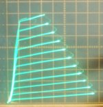
In some measurements I perceived a upward-curved gm plot for pentodes. If straigh "inclined" one is a perfect square-law, and a horizontally one is a unity-law, a 3/2 law between that, so a curved upwards is a more than square law, perhaps a 2.5 power law (less than cube law), for example? Or is another rule? What is the aspect for a cube law gm graph?
Some questions from a guy who don't have read all topics about power law🙂:
In some measurements I perceived a upward-curved gm plot for pentodes. If straigh "inclined" one is a perfect square-law, and a horizontally one is a unity-law, a 3/2 law between that, so a curved upwards is a more than square law, perhaps a 2.5 power law (less than cube law), for example? Or is another rule? What is the aspect for a cube law gm graph?
Plot the curves on a log-log graph. The 3/2s power law will have a slope of 1.5. A square law device will have a slope of 2 while cubic will be 3.
A resister would be linear, a slope of one on a log-log graph.
Hope a bit of math helps to understand.
A resister would be linear, a slope of one on a log-log graph.
Hope a bit of math helps to understand.
😱 oops, I forget to make some notes for it... Now I saved it. (for not asking same thing again and again...)The gm graph (versus drive V) is the 1st derivative of the power law formula. <snip>
But since I'm rusty with mathematics I don't resolve this formula in forum for cube law 😀
Last edited:
Thanks! I will play with it (when find some spare time). I presume that this will being good to identify power law by eye.Plot the curves on a log-log graph. The 3/2s power law will have a slope of 1.5. A square law device will have a slope of 2 while cubic will be 3.
A resister would be linear, a slope of one on a log-log graph.
Hope a bit of math helps to understand.
- Home
- Amplifiers
- Tubes / Valves
- More Ruminations on Screen Drive/Crazy Drive