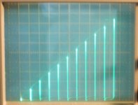
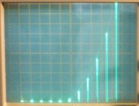
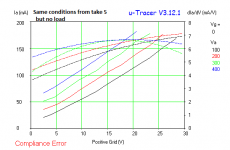
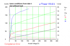
Here are some similar pics for the 26LX6 but:
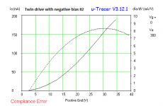
a) 17V heater, Twin drive (like before except low htr V)
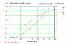
b) 26V heater, g1 drive, 90V on g2
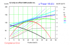
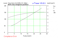
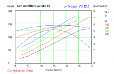
c) 26V heater, g2 only drive, 7 V steps
As you can see, reduced heater V causes the transfer to roll over some (a lot at even lower heater V)
g1 drive has a strong curvature upwards from strong gm variation
and the g2 curve has slight upward curvature from weak gm variation
(maybe just lower the heater V on the PL509 to straighten it out, only working if enough max current achievable though.)
..
a) 17V heater, Twin drive (like before except low htr V)
b) 26V heater, g1 drive, 90V on g2
c) 26V heater, g2 only drive, 7 V steps
As you can see, reduced heater V causes the transfer to roll over some (a lot at even lower heater V)
g1 drive has a strong curvature upwards from strong gm variation
and the g2 curve has slight upward curvature from weak gm variation
(maybe just lower the heater V on the PL509 to straighten it out, only working if enough max current achievable though.)
..
Attachments

Wow, very linear, in fact, this post #832 graph!
Soon I will play with the optimizations 🙂 is very tempting
Soon I will play with the optimizations 🙂 is very tempting
Last edited:
Here is the 26LX6 in Twin drive again, but with only g1 driven through the usual R divider, g2 is set at a fixed 27V. So showing the compensation effects from the g1 portion of Twin drive.
Attachments

Last edited:
re Lingwendil:
"so, i tie the cathode to ground (through an 1R to measure current?), grid to the junction between the rg2g1/rg1k resistors, bottom of the rg1k to my negative rail, or to ground directly? would i adjust for idle current of the sweep tube, at the gate of the follower that feeds the grids?"
With just 1 Ohm, either tie point for bottom of Rg1k should work. I have found only a few volts (up to -12V) useful for a neg. supply if used. Many tubes are happy with just 0V or cathode V. Yes, adjust idle voltage at the gate of the follower.
"I'm thinking of trying out some 2200R, and 1500R, and tying the bottom of the stack to a negative voltage from around 24 volts or so. Would this work, or would these values be too small? These would be driven by either a mosfet follower, small pentode, or maybe a triode. what would be a good current to idle through the resistors? would high wattage resistors be necessary?"
The divider resistors depend on the tube type, but those values should be useful for starting. Check the tube datasheet to see what maximum grid voltage will be needed on the selected Zpri load line. Then figure wattage of resistors with that voltage to 0 or to any minus supply across them. Very little current is drawn by g1. Double the resistor wattage then to be safe. Idle grid 2 voltage will be near zero since little idle current is needed through the tube.
Last edited:
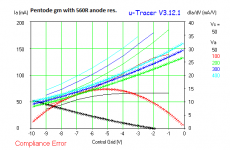
Optimization time...
Some steps, comparing G2 only, positive G1 and pentode mode
Some steps, comparing G2 only, positive G1 and pentode mode
Attachments
-
 PL509 pentode anode fixed varying g2-g1.png8.3 KB · Views: 127
 -
 PL509 pentode low current side.png11.3 KB · Views: 118
 -
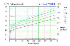 PL509 18Vg2 5k to G1.png12.3 KB · Views: 114
 -
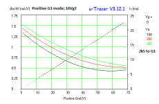 PL509 16Vg2 2k5 to G1 gm.png10.6 KB · Views: 106
 -
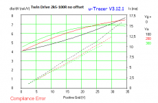 PL509 2k5-100R gm.png10.7 KB · Views: 114
 -
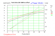 PL509 2k5-500R gm.png10.5 KB · Views: 111
 -
 PL509 1k-1k gm.png10 KB · Views: 118
 -
 PL509 2k5-0R gm after heating cycle.png10.7 KB · Views: 117
 -
 PL509 2k5-0R gm.png9.8 KB · Views: 378
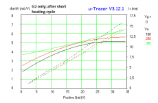
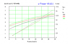
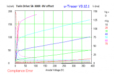
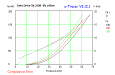
Last plots...
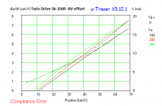
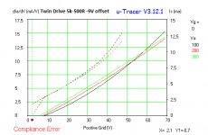
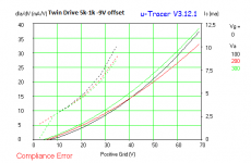
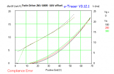
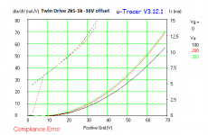
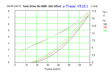
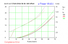
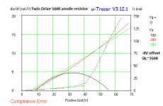
Now showing the steps including a offset in the end of G1 resistor.
If the µTracer is not playing tricks (instability), the -8V offset with 5k:250R is scary linear for a "semi-remote cut-off" tube like PL509 😛😀 and the resulting Ia/Va with varying drive is far more impressive than the original pentode curves
Attachments
-
 PL509 8Voffset 5k-300R 1.png10.4 KB · Views: 125
 -
 PL509 8Voffset 5k-250R.png9.7 KB · Views: 115
 -
 PL509 8Voffset 5k-250R gm.png10.4 KB · Views: 108
 -
 PL509 9Voffset 5k-500R gm.png10.9 KB · Views: 98
 -
 PL509 9Voffset 5k-1k gm.png10.1 KB · Views: 109
 -
 PL509 16Voffset 2k5-500R gm.png9.8 KB · Views: 100
 -
 PL509 16Voffset 2k5-1k gm.png9.9 KB · Views: 99
 -
 PL509 16Voffset 5k-500R gm.png9.8 KB · Views: 108
 -
 PL509 16Voffset 5k-1k gm.png9.8 KB · Views: 120
re: Lingwendil
Any negative rail would need to be adjustable, including down to zero V. The grid 1 compensation effects depend on grid 1 current draw. So nominally the R divider would just go to the cathode. The reason for some V offset is to correct for any internal tube thermo-electric potentials, from dissimilar metal joints in the lead wiring at high temp. (or to get additional non-linear compensation effects)
12AV5GA, OK. There were some Crazy/Twin drive curves and R values for the similar 6/12BQ6GA somewhere here. Starting back around post 464.
---------------------------------------------------------
re: DIYBras
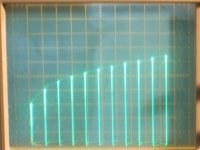
I was thinking about the plate current versus drive voltage curves (bars actually) shown on the curve tracer here, and realized that we are not looking at the same thing. Your tracer is plotting the results for a given plate V, or multiple V's. The tracer here is actually plotting the results (the peaks of the visible bars) along a load line of 650 Ohms. That's the current limiting resistor in this tracer for that Wattage/Voltage scale. So, reverting to a conventional plate curve graphic (plate I and V versus drive), those peaks are the ENDS of the plate curves when they hit the current limiting line.
The peak plate I versus drive V graphic here is still use-able, but it's just showing results for that specific load line. I need to install some banana plugs on the tracer so I can alter the limiting resistor to emulate other specific load lines. The present 650 Ohms would be equivalent to a 2600 Ohm P to P OT, so at least is in the practical range. But I would like to be able to do other OTs. (like 3300, 4000, 5000 etc.)
It IS interesting however that I am able to tweak the divider R values to get a linear response along that specific load line. The conventional plate I and V graphic versus drive V curves are not impacted, but they are just eye-balled as to linearity when adjusting the R divider values.
..
late edit:
Just seeing your latest curves, amazing. And you are able to tweak for linearity with a fixed plate V even. Looks like the Twin drive is QUITE adjustable! You may want to see if the results can be displayed for a selected load line, and then tweaked for linearity along that. No doubt different optimum R values will result along some load line.
..
Any negative rail would need to be adjustable, including down to zero V. The grid 1 compensation effects depend on grid 1 current draw. So nominally the R divider would just go to the cathode. The reason for some V offset is to correct for any internal tube thermo-electric potentials, from dissimilar metal joints in the lead wiring at high temp. (or to get additional non-linear compensation effects)
12AV5GA, OK. There were some Crazy/Twin drive curves and R values for the similar 6/12BQ6GA somewhere here. Starting back around post 464.
---------------------------------------------------------
re: DIYBras
I was thinking about the plate current versus drive voltage curves (bars actually) shown on the curve tracer here, and realized that we are not looking at the same thing. Your tracer is plotting the results for a given plate V, or multiple V's. The tracer here is actually plotting the results (the peaks of the visible bars) along a load line of 650 Ohms. That's the current limiting resistor in this tracer for that Wattage/Voltage scale. So, reverting to a conventional plate curve graphic (plate I and V versus drive), those peaks are the ENDS of the plate curves when they hit the current limiting line.
The peak plate I versus drive V graphic here is still use-able, but it's just showing results for that specific load line. I need to install some banana plugs on the tracer so I can alter the limiting resistor to emulate other specific load lines. The present 650 Ohms would be equivalent to a 2600 Ohm P to P OT, so at least is in the practical range. But I would like to be able to do other OTs. (like 3300, 4000, 5000 etc.)
It IS interesting however that I am able to tweak the divider R values to get a linear response along that specific load line. The conventional plate I and V graphic versus drive V curves are not impacted, but they are just eye-balled as to linearity when adjusting the R divider values.
..
late edit:
Just seeing your latest curves, amazing. And you are able to tweak for linearity with a fixed plate V even. Looks like the Twin drive is QUITE adjustable! You may want to see if the results can be displayed for a selected load line, and then tweaked for linearity along that. No doubt different optimum R values will result along some load line.
..
Last edited:
Umm, hmmm.
I just noticed that you got the --gm-- to conform to a linear ramp (using 5K:250 -8V offset), not the plate I.
So you have configured the tube to be a square law device! (HV Mosfet)
Gm should end up constant. (so plate current linear ramping versus drive V) That may not be possible with a constant plate V however, I don't know yet. But it does look quite possible along a practical load R line. (at least for 650 Ohms)
Some way to measure results along a fixed R load line there?
..
Last edited:
Square law
Square law? Cool 😎🙂
https://linearaudio.net/article-detail/2098
According with this, square law devices have it uses 😀🙂
Some other studies show a complete distorition cancellation for perfect square-law devices in class A PP use, since it have only 2H. And since we can tune the Twin Drive...
--
Probably is possible to apply a resistor in series with the µTraver anode switch, and maintaning the measurement node in anode. I will check this, and try to achieve some linear-gm graphs if so. Until now, I'm also unable to achieve linear gm with "zero ohms" loadline.
Later I will check the resulting FFT in a PP output jig from all "valid" biases (like pentode, G2 only, square-law and linear gm if posible).
A try with anode series resistor...
I put a 560R anode series resistor for emulating a load and see if this change the gm readings
Here is the results
Of course, tracer measurings not include the direct anode readings, since the resistor are "external" to it, ie. now is a part of anode. So with low anode voltages and high current, the tracer saturates, due to high drop in 560R resistor. And results in a curved gm trace.
One more time, I'm unable to achieve a constant-gm, but is easy to tune "perfect" square-law.
I thinkering about the linear gm: if a device has a constant eg. 5mA/V, ie., 5mA/V with 10mA and 100mA anode, this will lead to a conclusion: with very low anode currents, is impossible to sustain the 5mA/V, since we cannot have a transconductance with zero current (or power with zero ohms exists 😛😀😉🙂). So at some low current, gm will change, and leaves the constant (maybe the ideal point to put the idle current). In contrast, the "square-law" will be continuously changing gm with anode current, more or less like I expect from a real device (since almost all varies gm to some extent), but with a advantage to obeying a definite/constant law.
Probably a lack of sufficient offset will mask the very low current region, appearing to have gm here, in a real constant-gm.
Second though, I can imagine (but I can be wrong here, and missing something) that the tuning process only can "travel" between the G2 law and pentode law, so I have no idea how the constant-gm can be achieved (so I confess that I need to read all again to understand the constant-gm process). I assume the G2 law being the low exponent one and the pentode the high exponent one, and the square law being between that. All of this at "gm-graph-optics", of course...😉
Attachments

Hmmm, maybe I also check these plate current vs V input drive graph before attempting to straighen the gm graph 😱😀Umm, hmmm.
....
Gm should end up constant. (so plate current linear ramping versus drive V) That may not be possible with a constant plate V however, I don't know yet. But it does look quite possible along a practical load R line. (at least for 650 Ohms)
....
..
Because... in the one of firsts graphs, the "Crazy Drive 3k9:1k" shows a almost ruler-flat 300V anode current vs input step voltage, but gm is a curve. maybe this procedure straighen or maybe accentuates the gm curve, who knows...
"that the tuning process only can "travel" between the G2 law and pentode law, so I have no idea how the constant-gm can be achieved"
If both grid drives were by voltage mode, that would be true, but grid 1 is driven by an impedance, more like a current drive. (the Rg2g1) Being driven positive, it collects some current, and increasingly so. So that the g1 current drive becomes LESS effective at higher cathode current (unlike 3/2 or square law). This results in something more like a SQRT transfer function, for use as compensation of the g2 3/2 power law. (See below: The g1 function only, using the Twin drive setup.)
I switched the current limit on the tracer here to the 220 Watt scale (but reduced max V), which then uses a 140 Ohm load resistor. The previously straight plate current ramp versus drive V (at 650 Ohm load) then became slightly curved up, like for g2 only drive. I am unable to straighten it out by adjusting the pots, so looks like gm can NOT be made constant with constant plate V. That would be a vertical load line on conventional plate curves, so not a realistic application fortunately. I think the (internal) Mu of the tube limits the correction range of a current driven g1 (at the low current end), since it can only increase the total gm up till it hits the native (Mu x gm2) value.
A Square Law device requires class A operation to linearize in P-P, as you mentioned. So is of limited application. The constant gm device (at least for a load line) can run P-P in class B. Achieving a smooth class aB crossover would be problematic if the constant gm held all the way down to zero plate current. (the gm doubling issue for any conduction overlap) But, fortunately, the g2 gm drops out toward zero plate current in Twin drive (per 3/2 law derived), and the g1 is only able to maintain Mu (internal) times as much gm (as g2) at best, so it drops off eventually too. So compensation falling apart when g1 cannot fix g2 further, and so the total gm trailing off at low current. Making the smooth overlap possible that Mickeystan found around 16-20 mA idle for the 6DQ5.
In other words: Can look at the crossover region as where the low g2 gm has become in-effective from low current, but the g1 is still being driven by the (int.) Mu higher drive voltage of the HV driver stage. So it becomes a conventional g1 type crossover once the input signal drops 1/Mu below the usual V range. (for crossover of a g1 driven amp) It just becomes a conventional g1 driven amp then, but with a driver stage that has (int.) Mu higher V gain.
..
Attachments
Last edited:
Makes perfect sense now! 🙂) Yes, I missed something 🙄😀 ) Thanks for the explanations
The reducing gm also occurs in my "Positive G1 mode; 16Vg2 - 2k5 to G1" graph; the gm is reducing towards higher anode currents.
So basically more playing with the negative "extra" bias, and maybe a retouch to resistive divider, will led to the desired exponent combination, if tube permits (regarding cut-off), with anode resistor.
Great! I think I will buy that 40KG6 tube to try out here soon. And I need to add the binding posts for modifying the "load" (current limiting) R in the tracer. Then I will be able to accurately linearize the plate I versus drive V for common OTs.
I'm "guestimating" that the Mu(int.) factor inherent in Twin/Crazy drive allows the class aB crossover region to shrink by that much (ie, V input signal/Mu) versus conventional g1 drive amps. So the required idle current is shrunken similarly.
By the same thinking, conventional "audio tubes", with their higher internal Mu (like around 8), might be able to maintain the correction range over a larger plate current range, and achieve an even smaller crossover region (so maybe even less idle current).
That presumes that the Rg2g1 driven g1 can actually achieve the wider range tracking of the correction, and would of course require twice as much (or more) V drive from the driver stage. I was able to Twin drive a 6L6WXT earlier, but getting the correction "flattened out" was more problematic.
I just tried a lower Wattage scale on the tracer, 10 Watt with a 3K Ohm limiting R in the tracer, and I was able to linearize the transfer again. Looking good. However, a different Rg2g1 etc for a different load R.
Hmmm, Mickeystan's amp is using a 6.6K Ohm P-P OT I think. While the Twin compensation derived here for the 6DQ5 was for a 2.6K Ohm P to P OT effectively (4 x 650). So his R divider setup may be further improve-able yet.
...
Last edited:
More testings...
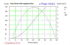
With negative extra biasing for G1, I'm unable to achieve linear Ia vs Twin Drive input voltage. when I changed to positive, ie. with G1 permanently sinking current, the tracer shows a very linear Ia/Vi ramp (4th graph)(excepting the measurement averaging errors from µTracer), albeit with not sooo linear gm, but far closer to a constant.
In this positive bias case, one needs a drive with capabilities to pull down all Twin Drive network, or better, to put a floating positive G1 bias, like a battery.
Since we have a node with permanent current, this manifests like a gm with zero bias, but in fact, the µTracer only source currents, so I cannot achieve negative driving at same positive graph.
And a additional problem to tune this is that since the µTracer takes time to measure points, one cannot tune on the fly; is one change at a time.
Well, very fun! But for now, I need to focus in some "unexpected" projects and work (unfortunately far more in work place...), so I take a "vacation" from tracer 😀🙂.
Attachments
Maybe just put some conducting LEDs in series with the Rg1k resistor to ground or cathode to get the positive V offset.
I have had to use a small positive bias for some tubes, like 36LW6, here. But only some. I think it may have to do with the construction materials/wires used in the tube, and high temperature thermal-electric junction effects.
Good to see the PL509 "straightening up". Some hope for it. I don't like buying expensive tubes to find out they are un-usable. The $1 and $4 tubes I got previously work like wonders with Twin/Crazy drive.
..
Last edited:
LED's in series, good idea! Or even something like a TL431 (variable zener) to adjust the bias (hmmm, maybe some LED's are more easy to install)
In my case, I "married" with the PL's, since I have almost 30 in a box, in working conditions (some like as new), and don't have other type. I acquired some time ago at very good prices, if we consider the actual market value.
Since I also looking for a excellent class-A amplifier (or perhaps only a different idea to make something distinct 😀), I'm also liked the "perfect square-law" achievement. I have a moderate sensitive Troel's TQWT, and most of time I listen at a not outrageuos volume, so is a calling to try it too. And I noted that the gm in square mode barely change with "normal" anode loadline change; is far less critic than the G1-G2 divider matching for achieving this... so, probably is very tolerant to loads like... speakers 🙂
I think you will find that just conventional grid 1 drive is fairly close to square law for TV Sweep tubes (and most higher gm tube types). Easier to drive too.
Might want to curve trace the PL509 for ramping gm using just grid 1.
That Square Law effect comes from grid1 wires to cathode local proximity effects, modifying the textbook 3/2 law. Grid 2 on the other hand is usually close to 3/2 power law. Low gm tubes with greater grid1 to cathode spacing, like some DHTs, can get closer to 3/2 power law on grid 1 (and plate), so can have quite constant Mu factors. UL and triode modded (higher gm) pentodes have considerable "roll-over" in their triode plate curves due to the power law mis-match.
I would love to find a means to fix the power law tracking for trioded pentodes and UL mode, but I haven't seen anything yet, except the equally non-linear load scheme used in the Aikido gain stage.
One can try to swamp out the square law of grid 1 by putting a 3/2 law thermionic diode under the cathode, but that lowers the Mu and raises Rp.
Another clever trick is using a negative Z load for a gain stage, which makes for a load line that tilts the other way, fixing the plate curve roll-over effectively. Typically using a positive feedback load bootstrap. No good for output stages though. But probably a good hint as to how to do it for a trioded pentode. Neg R or non-linear R needed somewhere, maybe the screen grid to plate connection.
..
Last edited:
Yes, I made it, in post#838: Ia/Vg tilts upwards and gm too. In this post, all graphs are in pentode mode. This resulting graphs shows a mixed law? (I ask since I have low experience to determine power laws)
My actual PL509 amp is operating at pentode mode albeit with some ~4% CFB.
Only in post#838, figure 7, the gm is a linear ramp (due to the #838 post you mentioned the square law), and it also caught my attention (if I don't confused things)
My actual PL509 amp is operating at pentode mode albeit with some ~4% CFB.
Only in post#838, figure 7, the gm is a linear ramp (due to the #838 post you mentioned the square law), and it also caught my attention (if I don't confused things)
- Home
- Amplifiers
- Tubes / Valves
- More Ruminations on Screen Drive/Crazy Drive