Well, firstly, I am amazed at how well the Twin/Crazy drive scheme works for virtually all the TV Sweep tubes tested. It is beyond all reasonable expectation.
I could guess that squared plate curve knees would be helpful (low screen current), but even bad tubes for that clean up remarkably well.
Low g2/g1 Mu, maybe helpful - maybe not. The 6L6 with Mu up at 8 is difficult to get compensated well. But then even the 12HL7 with a frame grid1 and Mu of around 30 works well in Twin/Crazy mode. Maybe its just low V for grid 2 that counts. The 12HL7 is non grid aligned with that frame grid, so that's not a factor. As one goes to higher grid2 V, then Rg2g1 has to get higher to avoid smoking grid1, and so it all slides back toward just grid 2 drive, assymptotically.
How close grid 1 is to the cathode, and how opaque it is to electron passage (so high grid1 current at +Vg1) could be a detrimental factor.
Probably more to it, I just don't know.
The non-linear Grid 1 current is the factor that is linearizing (counter-linearizing?) the non-linear (3/2 power law) of grid 2 voltage to current.
So making just one of the grids unusually linear might cause a problem.
..
Last edited:
It is your last point, particularly, that I had been wondering about! Lots to think about, thank you.
Fixed voltages on g1...
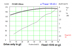
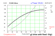
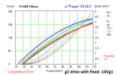
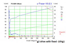
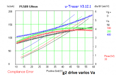
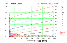
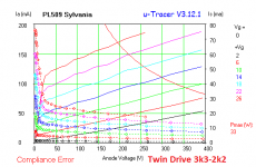
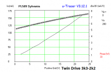
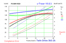
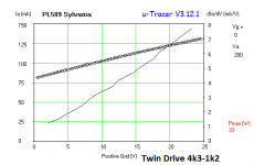
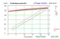
I noted a interesting phenomena: if I apply fixed DC on g1 I obtain a result not too far from Twin Drive (at least gm curves tend to bow to same direction), and the gm for negative g1 sometimes is scary like the kinked anode curves.
But fixed g1 drive seems to not complete the equation. Twin Driver make the curve more straigh. Is a good thing to explore...
PS.: about Compliance Error, is due to µTracer 200mA limit being exceeded.
Attachments
-
 PL509 Ultron pentode gm.png16.2 KB · Views: 413
 -
 PL509 Ultron 3k5-2k.png10.4 KB · Views: 70
 -
 PL509 Ultron g2 +5V6 g1 gm.png10.2 KB · Views: 70
 -
 PL509 Ultron g2 -5Vg1 gm.png10.5 KB · Views: 74
 -
 PL509 Ultron g2 -10Vg1 gm.png17.7 KB · Views: 87
 -
 PL509 Ultron g2 -10Vg1.png12.1 KB · Views: 402
 -
 PL509 Ultron g2 -20Vg1 gm.png10.3 KB · Views: 401
 -
 PL509 Ultron g2 gm.png16 KB · Views: 414
 -
 PL509 Ultron g2.png16 KB · Views: 408
Different tube types...
LATE DISCLAIMER: bear in mind my tracer limitations and possible device oscillations sometimes, and also that my Twin Drive attempts are not fully optimized. I optimize when I make my FFT tests in a amplifier. But the tendency is here.
Different brands, if not with defects, seems to need a fine tuning. Some are with different DC bias points if applied in a real amplifier, so take it with a grain of salt.
The "unknow" tube showed earlier probably have some defect, or have a internal mess. The grid 1 current test don't showed trouble.
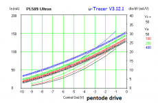
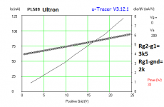
NOTE: Unless stated otherwise, the resistors from Twin Drive are show: first the Rg2-g1, then the Rg1-gnd.
LATE DISCLAIMER: bear in mind my tracer limitations and possible device oscillations sometimes, and also that my Twin Drive attempts are not fully optimized. I optimize when I make my FFT tests in a amplifier. But the tendency is here.
Different brands, if not with defects, seems to need a fine tuning. Some are with different DC bias points if applied in a real amplifier, so take it with a grain of salt.
The "unknow" tube showed earlier probably have some defect, or have a internal mess. The grid 1 current test don't showed trouble.
NOTE: Unless stated otherwise, the resistors from Twin Drive are show: first the Rg2-g1, then the Rg1-gnd.
Attachments

OOPS... I mean fixed BIAS g1 and g2 drive......
But fixed g1 drive ....
I should mention again that some Sweep tubes (but not many), like a 36LW6 I tested using the Twin Drive setup, had improved linearity in the low current range if I offset the voltage at the bottom of the Rg1k resister. (offset of couple of Volts from the cathode). I'm guessing this is due to some internal thermal-electric dissimilar metal bond in the internal lead wires. (getting hot under operation)
So if you see a linearity problem in the low current to cut-off range, could try a few volt variable offset (+ or -) in the Rg1k to cathode connection.
So if you see a linearity problem in the low current to cut-off range, could try a few volt variable offset (+ or -) in the Rg1k to cathode connection.
Smoking-amp,
About offset, last year I measured with offset at the end of Rg1-"gnd", when you recommended it. Worked excellent, even for making a perfect square law device. But this time I played with fixed offset g1 (positive and negative, like my last graphs) with g2 only drive (no g1 driving), to see if it lead for a usable result (uninspiring, to be honest). But anyway, you have tried this?
The "promising" results I've obtained for recent tube testings (excepting the Unknow tube) will encourage me to re-try the bias for Rg1 end, when I play again with.
Is a very bad luck I've tried just the strange or defective tube with Twin Drive before...
Hmmm, post #910, the graph from Tom is for negative biased g1 with g2 drive only, so my question: if you/someone have measured some time with g2 drive only and fixed positive g1 bias, ie. with eg. +5V instead of -33V?Smoking-amp,
.... But this time I played with fixed offset g1 (positive and negative, like my last graphs) with g2 only drive (no g1 driving), to see if it lead for a usable result (uninspiring, to be honest). ....
.
6DQ5 crazy drive amplifier update...
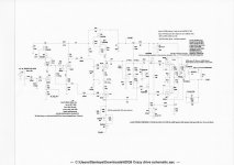
Hello fellow dyi's, I was getting bored following a long winter and wet spring, so I took the opportunity to revamp my crazy drive (twin drive if you prefer) amplifier. I gutted most of it and remade it with everything ahead of the source followers that drive the sweep tube output stage. I stayed with the same screen 2 to screen 1 divider ratio as it seems to work well. I did reference the bottom of the divider string to a minus 2.5v level as this helped distortion numbers. This amplifier likes to run at 36ma idle level or more. Lower idle values lead to worse distortion. I left my modeling info for distortion, feedback level and sensitivity on the ltspice attached schematic for your enjoyment. The amplifier sounds good to me and I have enjoyed playing some more with running sweep tubes with unconventional drive.
If you see ways to improve the design, share your thoughts and criticisms.
Best Regards Mickeystan
Attachments
Hi Mickeystan; it would be great to see your latest version but I can't read this kind of file. Were you idling at 9 ma before?
I think you may be the only one to complete a crazy drive push-pull (Smoking-amp hasn't said that he has finished his yet; he seems to spend a lot of time helping everyone else!). I was messing around today with some loadlines for a SE screen drive PL36 which I hope to convert to crazy drive once I get it working. I'm doing it SE because I don't have any suitable PP transformers in stock.
I think you may be the only one to complete a crazy drive push-pull (Smoking-amp hasn't said that he has finished his yet; he seems to spend a lot of time helping everyone else!). I was messing around today with some loadlines for a SE screen drive PL36 which I hope to convert to crazy drive once I get it working. I'm doing it SE because I don't have any suitable PP transformers in stock.

Driver for crazy drive should at least be a bit less difficult than for cathode follower output or even low mu triodes like 6AS7.
Mickeystan's latest Crazy Drive amp looks like it is handling all the known issues for Twin/Crazy drive. One thing to check for would be any spurious oscillation of the Mosfet followers when turning on/off etc. George had mentioned that problem. If the negative source swing is enough to turn the tube completely off, then that may not matter. Interesting that some neg. bias on the bottom Rg1k resistor improved the dist. for the 6DQ5.
Triode'ing sweep tubes on the curve tracer generally takes more step drive voltage than Twin drive.
Soon as I get past taxes, I should be able to get back to Twin drive experimenting. They say they are going to "simplify" taxes now. Hope that doesn't mean 200 pages of instruction manual now instead of 100 pages. Just like "simplified" software manuals, more chapters and tables. They will have to send a guide program soon.
Here is some modeling data I find interesting on the latest 6DQ5 crazy drive amplifier I posted on in thread #924. The modeled distortion results are better at higher output power with lower idle current on the sweep tubes. The opposite is true for lower output power. Here is some modeled data to consider. I like many others do not trust the simulated distortion numbers as they are always considerable better than reality. I will follow up and update the data with actual measured results in a day or two so we can see the difference. Bias pot range is 0 to 1.
Bias pots at .48 = 37.7ma idle = 0.007% at 1 watt rms & 2.66% at 39.1 watts rms.
Bias pots at .38 = 22.4ma idle = 0.168% at 1 watt rms & 1.97% at 39.1 watts rms.
Bias pots at .32 = 13.1ma idle = 1.424% at 1 watt rms & 1.46% at 39.1 watts rms.
Mickeystan
Bias pots at .48 = 37.7ma idle = 0.007% at 1 watt rms & 2.66% at 39.1 watts rms.
Bias pots at .38 = 22.4ma idle = 0.168% at 1 watt rms & 1.97% at 39.1 watts rms.
Bias pots at .32 = 13.1ma idle = 1.424% at 1 watt rms & 1.46% at 39.1 watts rms.
Mickeystan
With a lower value Schade Fdbk resistor, the output tube would have lower gain remaining, and would be more linearized itself, but the driver stage will have a harder time driving the higher input current required. Tubes are good at voltage, not so good at current.
Twin/Crazy drive is easier to drive (using TV Sweep type tubes, ie low g2 V). But more complex to design. N Fdbk still needed to lower output Z.
Twin/Crazy drive is easier to drive (using TV Sweep type tubes, ie low g2 V). But more complex to design. N Fdbk still needed to lower output Z.
With a lower value Schade Fdbk resistor, the output tube would have lower gain remaining, and would be more linearized itself, but the driver stage will have a harder time driving the higher input current required. Tubes are good at voltage, not so good at current.
Twin/Crazy drive is easier to drive (using TV Sweep type tubes, ie low g2 V). But more complex to design. N Fdbk still needed to lower output Z.
i
am looking at building a pp amp using the crazy drive, no need to provide regulated G2 supply and i think that drive requirements are still lower than if a straight Berning g2 drive is made...
Piano3,
Here is a copy of just the schematic. Sorry its not as good as it might be. I would make a better one if I knew how.
Mickeystan
how about a clean scan, my tired eyes are having some difficulty reading...
6DQ5 crazy drive amplifier....
AJT,
I have struggled to get a good clean copy of the schematic attached. I think it is due to the schematic taking up most of a single screen and my scanner not focusing as good as it should. The attached copy is likely the best I will be able to do. Hope you can read it OK.
Mickeystan
AJT,
I have struggled to get a good clean copy of the schematic attached. I think it is due to the schematic taking up most of a single screen and my scanner not focusing as good as it should. The attached copy is likely the best I will be able to do. Hope you can read it OK.
Mickeystan
Attachments
- Home
- Amplifiers
- Tubes / Valves
- More Ruminations on Screen Drive/Crazy Drive