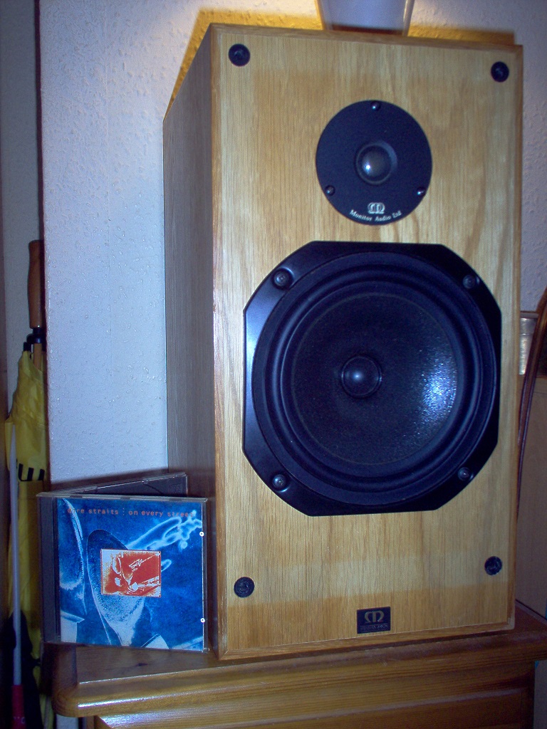
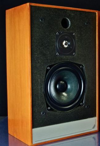
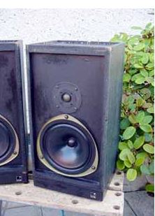
I picked up a pair of Mordaunt Short MS40 speakers from a charity shop today. They're the old 70's/80's brown ones!
I was hoping they would sound at least half decent so I could put them into my workshop and listen to the radio, but after hooking them up to my main system I was very unimpressed with them. Just seemed to be too much treble and no warmth coming from them. All the drivers were working, so either they're supposed to sound like that or the crossovers are a bit out of whack?
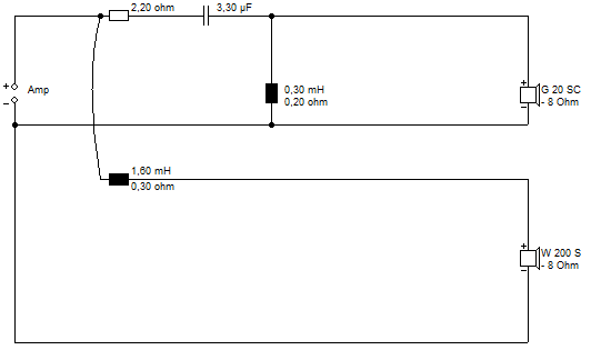
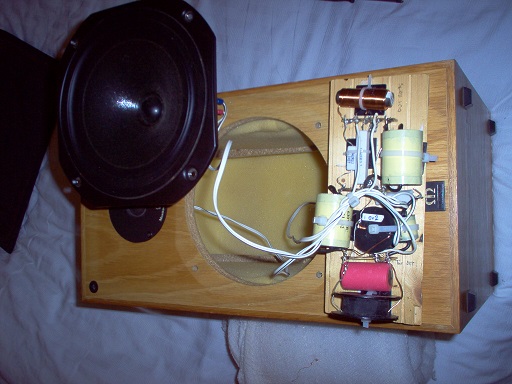
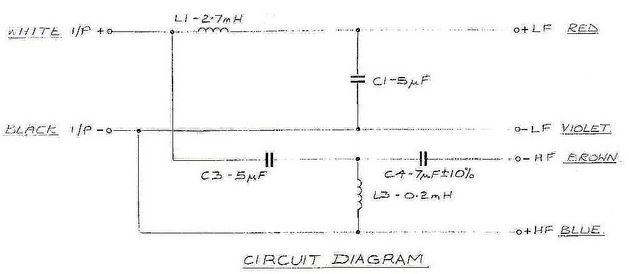
I've opened them up and taken a couple of photos and made a sketch of the crossover circuit, which has lead me on to two/three questions:


Cheers
[Oh, and any help making the images smaller until they're clicked on I appreciate as well 🙂 ]
I was hoping they would sound at least half decent so I could put them into my workshop and listen to the radio, but after hooking them up to my main system I was very unimpressed with them. Just seemed to be too much treble and no warmth coming from them. All the drivers were working, so either they're supposed to sound like that or the crossovers are a bit out of whack?
I've opened them up and taken a couple of photos and made a sketch of the crossover circuit, which has lead me on to two/three questions:
- I'm thinking I might just add some more resistance in series with the HF as a start to see if that helps re-balance the HF with the LF. Do you think it would be worthwhile replacing the electrolytics?
- What is the value of the second cap across the HF, one is marked 1.8k, the other 1.15j (see photos).
- Clearly MS are trying to tame this tweeter esp with the caps in parallel, but two caps??? Am I missing something here??? I triple checked it and that's definitely the layout???
Cheers
[Oh, and any help making the images smaller until they're clicked on I appreciate as well 🙂 ]
Last edited:
Initial reply:
British speakers of this vintage had a 'warm' sound.
Put in new electrolytics.
No need to replace film capacitors (like the siver and blue ones) or other crossover components.
Check the cone surround and spider of the bass driver for signs of detachment from the basket or signs of deterioration.
British speakers of this vintage had a 'warm' sound.
Put in new electrolytics.
No need to replace film capacitors (like the siver and blue ones) or other crossover components.
Check the cone surround and spider of the bass driver for signs of detachment from the basket or signs of deterioration.
Cheers, yeah that's what I was expecting, something warm sounding.
In the past I've had to replace caps to bring back some lost sparkle, but these seem like the opposite.
I'll see what I've got kicking around to replace them. I might have enough in the spares box to at least swap the ones on the HF side.
I did check the mid/bass surrounds and they seem fine, but that was good shout to check.
Any thoughts on the need for two caps across the HF?
I believe 1.15J means 1.15μF +/- 5% and 1.8K means 1.8μF +/- 10%.
Don't know why they have different values, must have been what MS had in stock at the time!
I can only suggest that the blue caps were parallelled up with the 0.47μF ones because a single cap of the required value was not available.
One combination adds to 1.62μF and the other 2.27μF. If replacing the parallel combinations, I'd probably go for single 2.2μF caps.
I'll just add that a faulty electrolytic in parallel with the bass driver can totally mess up the bass response. That's the first one I'd go for!
I think this model went through a few variations, particularly on tweeter.
A good ol' 8" bass in a big box has loads of possibilities! Monitor Audio R300-MD:
I ripped out the tweeter and fitted a Monacor 92mm HT22-8, cheap as chips from Blue Aran: Monacor HT-22/8 10W Cone Tweeter from Monacor PS6.46
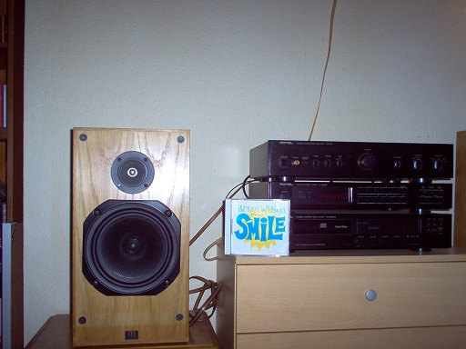
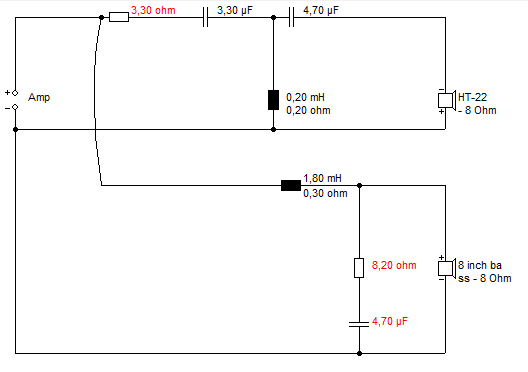
Very musical! Wilmslow Audio have some smallish 250V polypropylene capacitors. Should fit on the board.
A good ol' 8" bass in a big box has loads of possibilities! Monitor Audio R300-MD:
I ripped out the tweeter and fitted a Monacor 92mm HT22-8, cheap as chips from Blue Aran: Monacor HT-22/8 10W Cone Tweeter from Monacor PS6.46
Very musical! Wilmslow Audio have some smallish 250V polypropylene capacitors. Should fit on the board.
I think you could lose those shunt capacitors. Can't do any harm, though I'd have to model it to see how they work. Software | Visaton
I'd think the woofer sounds a bit peaky with a 10uF shunt, especially if the bass coil is small. Nothing stopping you turning the tweeter down with a bigger resistor. Every ohm you add takes it down a dB.
It's probably crying out for a better tweeter and bass circuit. Not much wrong with the treble filter apart from those awkward shunt capacitors.
So I replaced all the electrolytics on LF and HF with some known good, audio quality parts from my spares bin.
No dice....they sound the same as before.
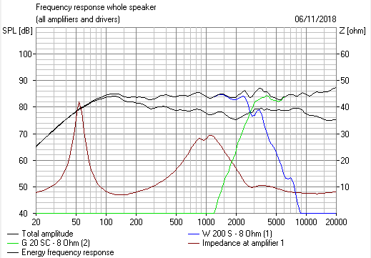
I have taken a REW measurement from 120Hz to 20KHz:

Looks to me like the midrange is running about 3db up?
Please do butt in with opinions, I'm not that experienced with these REW measurements either so I may be interpreting it wrong?
Steve, I think your right, a little bit of faffing, maybe a new tweeter and these will probably start sounding quite good. I'm not sure I'll be going that far with these.
I'm thinking I might go with my original plan, add some more resistance to the LF section to pull it down a bit. At the end of the day they'll be going into my workshop so undemanding warm sounding speakers is what I'm after, not super fidelity.
No dice....they sound the same as before.
I have taken a REW measurement from 120Hz to 20KHz:
Looks to me like the midrange is running about 3db up?
Please do butt in with opinions, I'm not that experienced with these REW measurements either so I may be interpreting it wrong?
Steve, I think your right, a little bit of faffing, maybe a new tweeter and these will probably start sounding quite good. I'm not sure I'll be going that far with these.
I'm thinking I might go with my original plan, add some more resistance to the LF section to pull it down a bit. At the end of the day they'll be going into my workshop so undemanding warm sounding speakers is what I'm after, not super fidelity.
It depends on the size of the bass coil, but I had some luck with about 0.8mH bass coil and a shunt of 7.5R and 8.2uF with an 8" bass. Not much bafflestep there, but I don't mind that sound with the speakers close to a wall.
It's really using the woofers natural rolloff, with a bit of impedance correction. Should take the 1kHz to 3kHz area down a couple of dBs. Cheap entertainment anyway. Values aren't to critical.
It's really using the woofers natural rolloff, with a bit of impedance correction. Should take the 1kHz to 3kHz area down a couple of dBs. Cheap entertainment anyway. Values aren't to critical.
I just had the old monitor audio's apart to remind myself what I did with them. Currently have SEAS 19TAF/G tweeters. SEAS make so many!
Seas Tweeters, Prestige,Excel, Exotic and Vintage Replacement ranges
They are mostly on Classic FM duty these days.
Good phase alignment!
The hobby is great fun! Couple of goodish woofers here:
Seas P21RE/P H0942-08 Woofer. H0313 2015 remake for closed box.
Vifa P21W0-20-08 Woofer For reflex.
Seas Tweeters, Prestige,Excel, Exotic and Vintage Replacement ranges
They are mostly on Classic FM duty these days.
Good phase alignment!
The hobby is great fun! Couple of goodish woofers here:
Seas P21RE/P H0942-08 Woofer. H0313 2015 remake for closed box.
Vifa P21W0-20-08 Woofer For reflex.
Were they originally meant to be mounted against or close to a wall or corner to bring the bass up a bit more?
Your point about 3dBs to much midrange (or maybe a bit more) is spot on, so possibly a bit more inductance on the bass would give more baffle step compensation and start to get you some warmth. Once you are happy with that then you will probably have to play with the tweeter padding resistor to match to taste or get you a flat or shelving response in REW.
It would be worth trying to find some data and hopefully a review with frequency response graphs to compare.
If the tweeters are early metal domes maybe the shunt capacitors were there to help tame the top end or help with overall impedance, just a thought.
IIRC, old Mordaunt Short are quite bass light. Small bass coils, as you say.
I have tracked down the speaker:
MORDAUNT SHORT MS-40 | Classic Hi-Fi
The 8" bass seems to be an old Dalesford DSB 208 paper unit:
stereonomono - Hi Fi Compendium: Mordaunt-Short DSB 208
Dalesford were more famous for some polypropylene basses back in the BBC heyday.
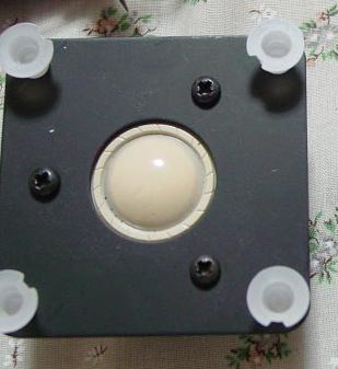
The tweeter looks like a mylar unit with a phase plate. Doesn't help much really. The crossover and tweeter is dubious IMO. 😀
We could be looking at voice-coil rubbing in a speaker this old. Turn the bass 90 degrees is the best quick fix, IMO.
I have tracked down the speaker:
MORDAUNT SHORT MS-40 | Classic Hi-Fi
The 8" bass seems to be an old Dalesford DSB 208 paper unit:
stereonomono - Hi Fi Compendium: Mordaunt-Short DSB 208
Dalesford were more famous for some polypropylene basses back in the BBC heyday.
The tweeter looks like a mylar unit with a phase plate. Doesn't help much really. The crossover and tweeter is dubious IMO. 😀
We could be looking at voice-coil rubbing in a speaker this old. Turn the bass 90 degrees is the best quick fix, IMO.
Last edited:
Think I've figured out what the tweeter is. An Isophon KK10/ca:
This is the later Pageant 2, but looks familiar, eh?
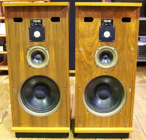
The Isophon KK8 was very popular in the 70's too, with an aluminium mounting plate:
I had some in the Chartwell PM400, and they were very crisp sounding with a 0.5A fuse to protect them:
Mylar or polycarbonate tends to brightness above 5kHz, so that is probably what the shunt capacitors are trying to fix in the tweeter filter.
DT 94 - 8 Ohm | Visaton
The KK8 was used in a lot of two-ways, here the Monitor Audio MA5 with a bextrene bass:
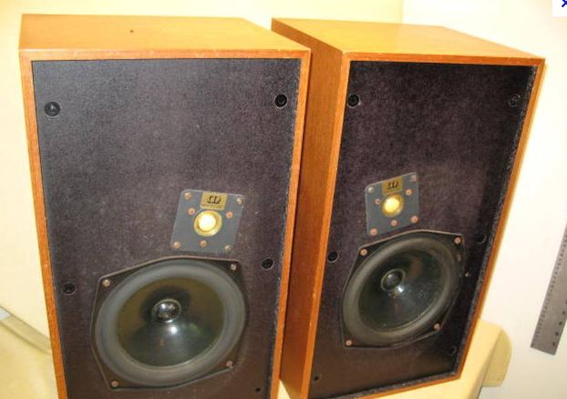
So really, this speaker ought to sound quite good.
This is the later Pageant 2, but looks familiar, eh?
The Isophon KK8 was very popular in the 70's too, with an aluminium mounting plate:
I had some in the Chartwell PM400, and they were very crisp sounding with a 0.5A fuse to protect them:
Mylar or polycarbonate tends to brightness above 5kHz, so that is probably what the shunt capacitors are trying to fix in the tweeter filter.
DT 94 - 8 Ohm | Visaton
The KK8 was used in a lot of two-ways, here the Monitor Audio MA5 with a bextrene bass:
So really, this speaker ought to sound quite good.
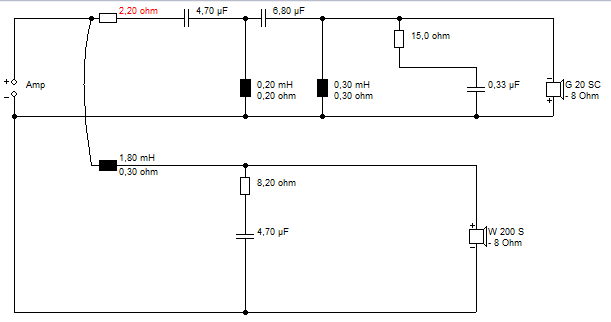
I was just looking at this Mordaunt Short MS40 circuit in Boxsim, and it is a bit of a disaster.... 😱
Third order tweeter, 2.2R, 3.3uF, Coil probably near 0.2mH, 5uF and this weird parallel shunt around 2-4uF.
Second order bass, coil and 10uF, probably peaky without some series resistance.
A much better way to tame the (bright?) tweeter is a Zobel next to it. 7.5R plus about 2.2uF in series. Impedance doesn't drop to 2.2R at high frequency. Which must be better for the amp, and still gives near 3dB attenuation at the top. I've done this sort of thing with the plastic Visaton DT94 and it works.
Bit of work on the bass too, I think. But not difficult.
Tons of good detective work there from system7.
Plus the fact that you cans see what's going on should mean that these can be brought back into shape quickly.
Do you have a way of measuring the inductors, and one final quick thought what happens to the sound if you reverse the tweeter, a REW plot might be interesting of the reversed configuration as well?
Thanks Steve for all that info, I'm probably going to spend the rest of the day digesting it 🙂. I've messed around with speakers before but not really got into passive crossovers much so I'm on a bit of a learning curve so please bear with me.
I don't currently have an LCR meter, but I think I'm just about to go on a spending spree 😀
Currently I've got a cheap (£20) LCR meter in my ebay cart, and 4x 0.4mH air inductors (AC071) in my Falcon acoustics cart. Before I pull the trigger I wanted to get some opinions if these would be good enough / give me enough options to mod the crossover into something that works a bit better for me?
For this morning I'm going to follow up on Raymondj's comments and take a measurement with them jammed into the corner, and another with the tweeter's connections reversed.
Are you planning on adding additional inductance at 0.4mH at a time?
It does work but you are wasting some energy in the added resistance. Some would say go for a low Resistance 1mm/1.2mm wire and 2.0mH as a bass inductor.
With your new LCR meter you can unwind the 2mH a few turns at a time after each test to get the optimum value of inductance. You will need to scrape of the lacquer to make a good connection and a good soldering iron and flux solder to re tin the ends each time. Take note of how much wire you remove so you can do the same thing to the other Inductor, once you are happy with the sound. You can build precision matched Inductors with the help of your meter.
Looking at Steve simulations which are not 100% guaranteed to match you driver he shows that 1.8mH or so should work with the 80s technology driver.
I have often found with older 8ohm drivers, once you get to trying a 2.2mH they will loose the plot sound wise, and often I end up around 1.6m- 2.0mH.
Once sorted I am sure it will be a good speaker.
Have a well ventilated room when you are burning the flux off and please don't breath the solder fumes either.
A bit early I know, Happy New Year.
Raymond, perfect....that was exactly the sort of advice I was looking for. You were right I was planning on just having some inductance that I could add, but your 2.0 mH and unwind suggestion is far more sensible.
As I'm paying the postage do you think it wise to get some other higher inductance cored jobbies for options on the HF side? If so what size would you recommend?
And a happy new year to you and everyone else. 🙂
As I'm paying the postage do you think it wise to get some other higher inductance cored jobbies for options on the HF side? If so what size would you recommend?
And a happy new year to you and everyone else. 🙂
Also here are the results from this mornings playing about.
The placement tight to the wall is making a big difference to the bass, and helping out with the warmth alot. Still left sounding a taj hollow, and the tweeter is still a little too bright up top (for me, for this application). I'm supprised to see such a lift in the readings (+6db I recon), I can definatley hear a big jump, but thought that baffle step correction usually maxed out at about 6db and thats in an anochonic chamber?
Swapping the connections to the tweeter makes them sound odd, cant quite explain it, but I can clearly see on the REW plot.
New basline about 30cm or 1ft from side and rear walls
Tight to the side wall and 15cm, or 6" from rear wall
Original position, tweer connections reversed
The placement tight to the wall is making a big difference to the bass, and helping out with the warmth alot. Still left sounding a taj hollow, and the tweeter is still a little too bright up top (for me, for this application). I'm supprised to see such a lift in the readings (+6db I recon), I can definatley hear a big jump, but thought that baffle step correction usually maxed out at about 6db and thats in an anochonic chamber?
Swapping the connections to the tweeter makes them sound odd, cant quite explain it, but I can clearly see on the REW plot.
New basline about 30cm or 1ft from side and rear walls
An externally hosted image should be here but it was not working when we last tested it.
Tight to the side wall and 15cm, or 6" from rear wall
An externally hosted image should be here but it was not working when we last tested it.
Original position, tweer connections reversed
An externally hosted image should be here but it was not working when we last tested it.
These are good measurements, Adam. Sort of thing I get a bit lazy about... 😱
I have seen a lot to encourage some minor modifications. The woofer looks remarkably similar to my old predictable MA Elac unit. Magnet size, cone material, 26mm voicecoil diameter...
These days magnets and coils are bigger and more reflex oriented, which may be a step backwards for good midrange.
It is usually quite easy to unwind coils, which are often just enamelled wire wound round a bobbin and taped up, it being that inductance is the square of the number of turns:
Air Cored Inductors
These Blue Aran MKP capacitors look useful enough:
Blue Aran - The UK's no.1 Loudspeaker Component Stockist > Speaker Components > Crossover Components > Capacitors
0.33uF and 0.68uF are useful for tank notches on the bass and Zobels.
A few 7W ceramic resistors are handy too. I like to have 1R, 2.2R, 3.3R, 4.7R, 6.8R and 15R to hand.
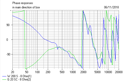
These third order crossovers are usually negative polarity, being about 5cm offset between tweeter and 8" bass, at 3kHz, which is half a wavelength:
That is a KEF Celeste 3, which must be bass heavy. It gets away without shunt resistance because the coil is so big.
I have seen a lot to encourage some minor modifications. The woofer looks remarkably similar to my old predictable MA Elac unit. Magnet size, cone material, 26mm voicecoil diameter...
These days magnets and coils are bigger and more reflex oriented, which may be a step backwards for good midrange.
It is usually quite easy to unwind coils, which are often just enamelled wire wound round a bobbin and taped up, it being that inductance is the square of the number of turns:
Air Cored Inductors
These Blue Aran MKP capacitors look useful enough:
Blue Aran - The UK's no.1 Loudspeaker Component Stockist > Speaker Components > Crossover Components > Capacitors
0.33uF and 0.68uF are useful for tank notches on the bass and Zobels.
A few 7W ceramic resistors are handy too. I like to have 1R, 2.2R, 3.3R, 4.7R, 6.8R and 15R to hand.
These third order crossovers are usually negative polarity, being about 5cm offset between tweeter and 8" bass, at 3kHz, which is half a wavelength:
That is a KEF Celeste 3, which must be bass heavy. It gets away without shunt resistance because the coil is so big.
- Home
- Loudspeakers
- Multi-Way
- Mordaunt Short MS40 Crossover Help