Steve, going back and re-reading your posts I have a couple of questions.
Please explain what you mean by sounding peaky with the 10uF?
I have downloaded the software you linked to, I'm really keen to be able to run the simulation myself. What speakers would you recommend I select from the library to best represent my drivers?
In post #12 you mentioned about rubbing voice coils that I initially missed. I did check them and didn't feel or hear anything with a gentle push.
I think I'm going to try your suggestion of 7.5R and 2.2uF across the HF, but want to run the sym myself first before I make the mod 🙂
I can usually set up a sim in 5 minutes in Boxsim: Software | Visaton
You choose, say two driver setup, and model a common enclosure the size of your speaker.
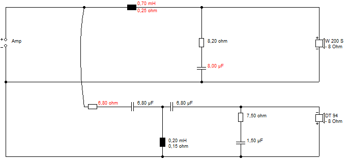
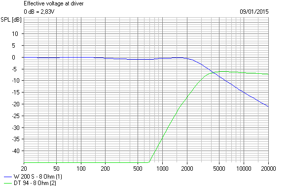
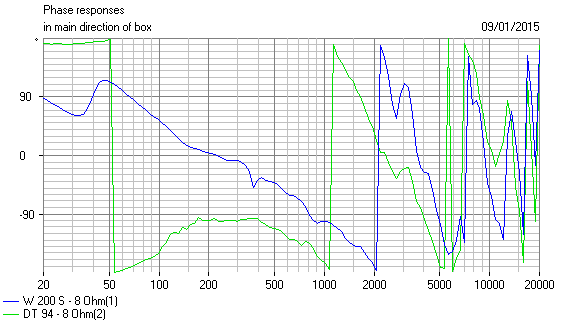
Then choose a couple of drivers, IIRC, say a W200S-8 and DT94-8 here.
Place them on the baffle.
Now go to visaton and check the bass loading for the W200S: W 200 S - 8 Ohm | Visaton
About 30L, so 39Hz tuning, I reckon. Boxsim allows for box diffraction as default. It has an optimiser which, when you mark components in red, will line it all up rather well.
Now input your crossover and see how it works. I found that capacitor shunt on the tweeter wrecked high frequency impedance. The peaky bass at 3kHz is what happens with a small bass coil and a big shunt (10uF) capacitor. It interacts with the bass speaker which has a substantial inductance.
This is why online calculators are a bit rough and ready: 2-Way Crossover Calculator / Designer
You really need to use the DC resistance of the divers, usually 6 ohms, and impedance correction on the bass, which is 7.5R and 39uF for the high inductance W200S-8. to use these things. And bafflestep is not included.
Your basses will be lower inductance, I reckon. Online tweeter circuit calculations are often quite good and work very flat on impedance. You need Butterworth third order, 3kHz and 6 ohm here at a guess.
You choose, say two driver setup, and model a common enclosure the size of your speaker.
Then choose a couple of drivers, IIRC, say a W200S-8 and DT94-8 here.
Place them on the baffle.
Now go to visaton and check the bass loading for the W200S: W 200 S - 8 Ohm | Visaton
About 30L, so 39Hz tuning, I reckon. Boxsim allows for box diffraction as default. It has an optimiser which, when you mark components in red, will line it all up rather well.
Now input your crossover and see how it works. I found that capacitor shunt on the tweeter wrecked high frequency impedance. The peaky bass at 3kHz is what happens with a small bass coil and a big shunt (10uF) capacitor. It interacts with the bass speaker which has a substantial inductance.
This is why online calculators are a bit rough and ready: 2-Way Crossover Calculator / Designer
You really need to use the DC resistance of the divers, usually 6 ohms, and impedance correction on the bass, which is 7.5R and 39uF for the high inductance W200S-8. to use these things. And bafflestep is not included.
Your basses will be lower inductance, I reckon. Online tweeter circuit calculations are often quite good and work very flat on impedance. You need Butterworth third order, 3kHz and 6 ohm here at a guess.
Last edited:
I just dug up an old BW3 build here along those lines:
It worked. I was experimenting with 90 degree phase alignment which can improve power response. 😀
It worked. I was experimenting with 90 degree phase alignment which can improve power response. 😀
System 7 has provided you with a wealth of info there, and it will take a little time to digest, unless it is close to your work or your hobby.
He did take some time to explain stuff which will be a great help along the way.
I have started my celebrations early so take my response's with a pinch of salt.
I am reluctant to recommend a tweeter starting inductor, as I don't know enough about it. It is a few years old and if I say buy a 0.5mH and then start unwinding it, may mean its get too much low frequency energy and goes silent or becomes damaged. Getting a replacement will be tricky. It was a well respected, if not a pinnacle of tweeter design for the time. Basically, I imagine as well the tweeter circuit should be about right, after all they have survived all these years.
Test the bass with differing inductor values once you are back in the ballpark. stop measure and see what you have. Then try another ohm or so on the tweeter resistor I am sure you will get a reasonable response quickly.
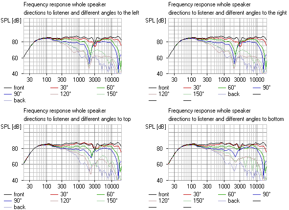
Your graphs with tweeter out of phase suggest a crossover around 3Khz to me, so as you tune for a gentle decline or flay to that frequency just keep watching how the 3Khz region behaves.
Good luck and keep us posted.
He did take some time to explain stuff which will be a great help along the way.
I have started my celebrations early so take my response's with a pinch of salt.
I am reluctant to recommend a tweeter starting inductor, as I don't know enough about it. It is a few years old and if I say buy a 0.5mH and then start unwinding it, may mean its get too much low frequency energy and goes silent or becomes damaged. Getting a replacement will be tricky. It was a well respected, if not a pinnacle of tweeter design for the time. Basically, I imagine as well the tweeter circuit should be about right, after all they have survived all these years.
Test the bass with differing inductor values once you are back in the ballpark. stop measure and see what you have. Then try another ohm or so on the tweeter resistor I am sure you will get a reasonable response quickly.
Your graphs with tweeter out of phase suggest a crossover around 3Khz to me, so as you tune for a gentle decline or flay to that frequency just keep watching how the 3Khz region behaves.
Good luck and keep us posted.
Cheers guys for all your input 🙂
I have ordered some parts now, so will report back in a week or so once they have turned up and I've had a play 😀
I have ordered some parts now, so will report back in a week or so once they have turned up and I've had a play 😀
I'm sure this will turn out well. 🙂
Here's a good resource if you are new to Visaton Boxsim:
3 Wege – Boxsim Projektdatenbank
This is a huge databank of Visaton Projekte files you can download and put in the projekte folder of Boxsim. They then open straightaway. Modify to your heart's content! Quality varies a bit, being amateur and professional builds.
Each Visaton driver tends to list Visaton Kits they are used in:
W 200 S - 8 Ohm | Visaton
There aren't any 8" plus 1" projects, but we know how to do those. I had some issue with an outdated security certificate, but just ignored it.
Another good resource is Madisound's Library of designs.
Take a Vifa P21W0-20-08 Woofer and a Scanspeak D2606/922000 Tweeter.
And there is a goodish filter!
https://www.madisound.com/library/p21wo20-d2606-9220-2way-passive-crossover-design/
You could do that if all else fails, and I bet it's rather good. 😎
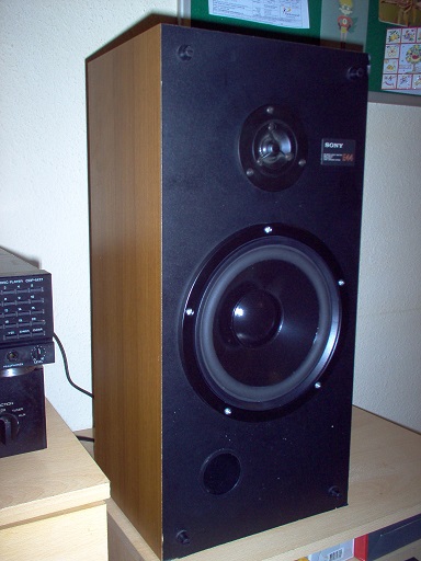
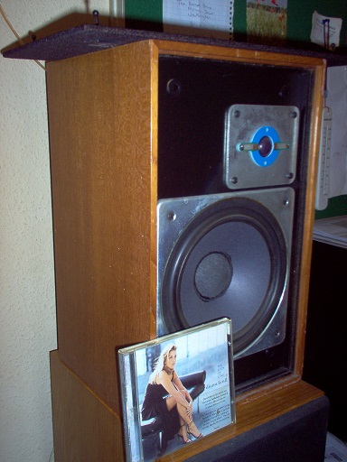
Were they originally meant to be mounted against or close to a wall or corner to bring the bass up a bit more?
I think this is the correct answer. MS speakers at that time were designed with no baffle step and were intended to be placed against the wall.
Martin Colloms once came up with a low-level step filter to correct the response of the MS100.
That filter applied to the small MS100 closed box speaker of the late 80s which belonged to the generation that followed the older and larger MS40 reflex loaded speaker which is the subject of this thread. The MS100 was certainly designed for close to wall mounting, and no doubt the earlier MS40 will also benefit from being so located.Martin Colloms once came up with a low-level step filter to correct the response of the MS100.
Attachments


I think this is the correct answer. MS speakers at that time were designed with no baffle step and were intended to be placed against the wall.
Agreed.
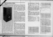
Adam, I've found a review of the MS40 in my 1985 edition of the Hi-Fi Choice Best Buy magazine.
Thank you Galu. Really interesting, especially as I'm getting some very similar measurements.
And amusingly as they seem to claim that the fuse and tweeter lever resistor are "two special protection devices, .... thermally operated and changing from very low to high resistance under overload"
Hahaha, some things don't change!
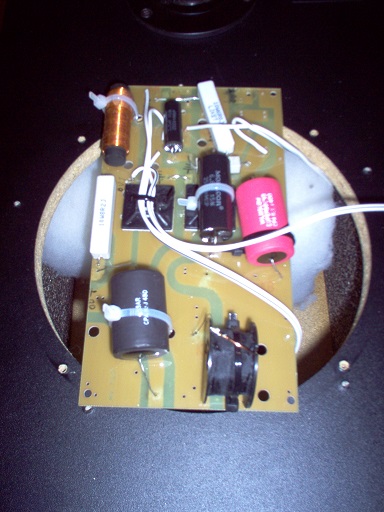
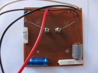
My new LCR meter turned up a couple of days ago and it has sparked some measuring!
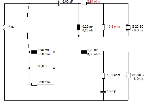
Here is the updated crossover network values

Here is the updated crossover network values
Also, having been playing around with boxsim I decided that the packaged speaker data wasn't really representative so I took out the Woofer and made some measurements.
Nearfield (ish....6cm) DSP 200 (woofer)

Impedence

From this I make the Qms = 3.76; Qes = 0.42; Qts = 0.38 (I’m still sanity checking these...... so many different methods online for working these out from the impedance, but nearly all of them have a mistake or omission in them!).
I haven't measured Vas, but then I don't intend to change the reflex volume, and the value of 110 that was left in from a previous 20cm speaker isn't giving me bad results (sim vs measured).
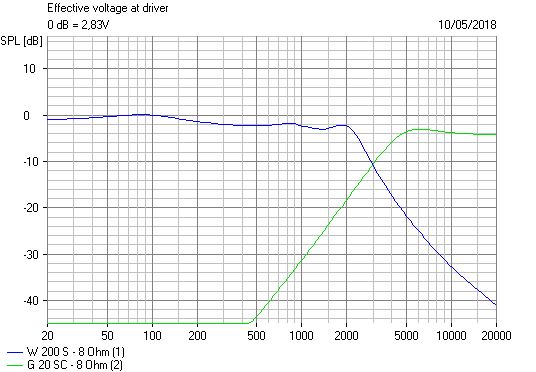
So I have ended up with this (Boxsim upper, REW measurement lower)

I'm pretty happy with that, the tweeter is still one of the boxsim packaged ones, but seems to be fairly reasonable representation.
Still waiting for the new inductors to arrive, so will report back once I have had a play with them. 🙂
Nearfield (ish....6cm) DSP 200 (woofer)
Impedence
From this I make the Qms = 3.76; Qes = 0.42; Qts = 0.38 (I’m still sanity checking these...... so many different methods online for working these out from the impedance, but nearly all of them have a mistake or omission in them!).
I haven't measured Vas, but then I don't intend to change the reflex volume, and the value of 110 that was left in from a previous 20cm speaker isn't giving me bad results (sim vs measured).
So I have ended up with this (Boxsim upper, REW measurement lower)
I'm pretty happy with that, the tweeter is still one of the boxsim packaged ones, but seems to be fairly reasonable representation.
Still waiting for the new inductors to arrive, so will report back once I have had a play with them. 🙂
Your crossover board must pre-date MS's fitting of the 'Positec' protection devices.
I did not know about these! As you say, mine must pre-date the review as they certainly don't have anything like that on them. I'll reluctantly take back my 'marketing bs' claim for now.........I'm sure it wont be long before I get to bring it out again! 😀
I'm waiting with bated breath!
Adam seems to be very good at this old measuring business!
Very smooth Dalesford 8" woofer really. Medium inductance at 25 ohms @ 10 kHz.
That innocuous looking bump at 1,3kHz can come back to bite you when you filter it. It's a surround issue, where the wave hits the cone edge and it's a pain.
Let's recall that most filters look like this mathematically:
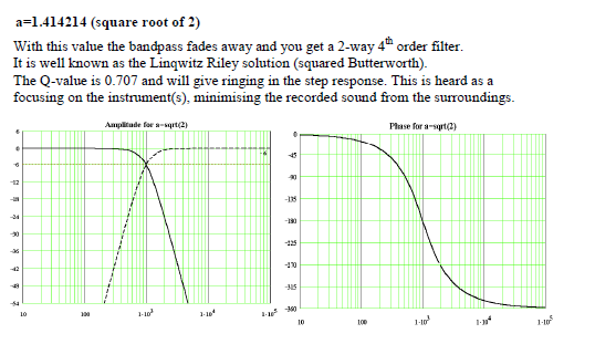
What that doesn't include is bafflestep, time-alignment, phase-alignment and impedance and breakup problems which often force you to a rethink. 😡
While we hang around, here's a couple of goodish paper 8" plus 3/4" mylar solutions:
Wharfedale Shelton XP2:
The electrical response is a truly impressive 12dB/octave, with a tiny notch on the 1.3kHz surround issue, and an excellent sounding speaker IMO.
This is the Wharfedale Laser 90B:
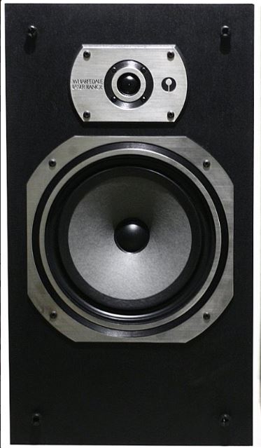
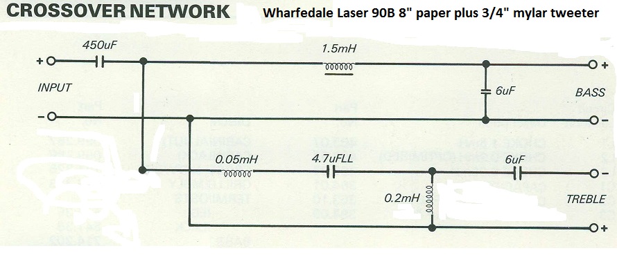
Another speaker full of interest and ideas. The 450uF electrolytic gets a bit more bass out of a 17L closed cabinet than you might expect. The 0.05mH coil just rolls off the mylar tweeter a bit. Otherwise reverse polarity 3rd order BBC style.
Adam seems to be very good at this old measuring business!
Very smooth Dalesford 8" woofer really. Medium inductance at 25 ohms @ 10 kHz.
That innocuous looking bump at 1,3kHz can come back to bite you when you filter it. It's a surround issue, where the wave hits the cone edge and it's a pain.
Let's recall that most filters look like this mathematically:
What that doesn't include is bafflestep, time-alignment, phase-alignment and impedance and breakup problems which often force you to a rethink. 😡
While we hang around, here's a couple of goodish paper 8" plus 3/4" mylar solutions:
Wharfedale Shelton XP2:
The electrical response is a truly impressive 12dB/octave, with a tiny notch on the 1.3kHz surround issue, and an excellent sounding speaker IMO.
This is the Wharfedale Laser 90B:
Another speaker full of interest and ideas. The 450uF electrolytic gets a bit more bass out of a 17L closed cabinet than you might expect. The 0.05mH coil just rolls off the mylar tweeter a bit. Otherwise reverse polarity 3rd order BBC style.
Ok, time for an update. My inductors turned up yesterday, and I've been playing around with them 😀.
Out of the box they were 1.95mH, but that was a bit too much (which was expected). The presence / soundstage was quite diminished and just starting to sound a tiny bit hollow.
So far I've unwound them to 1.7 mH, which has brought back a lot of the presence / soundstage whilst keeping the 'added warmth' from low down. I've also upped the tweeter padding resistor to 3R, which has brought the HF down a smij and in line with the midrange.
Sensitivity is obviously down, but I was surprised by how small the overall perceivable change was.
I'm really happy with them 🙂. They could possibly benefit from the inductors being unwound a tiny bit more, to say 1.5 / 1.6 mH, (but it's not as easy to put back on once it’s been cut off) and I think the bump at 1.3 KHz that Steve pointed out might start to become more prominent and require a notch (a future mod maybe).
I'll see how I go with them in the current trim, but like I said I'm pretty happy with them now. I'll jam them into the corners of my workshop for some nice, slightly overblown / boomy bass and lightly rolled off top end. That means I can bop along to an FM radio station and/or crappy internet audio while I work without the low-res being too noticeable.
Here is the final back to back (both away from the wall):
That's really great news.
Very glad that you like them, as you say a subtle change, you certainly got the baffle step sorted. It can take ages to voice speakers for your own tastes.
Enjoying some relaxed listening for the time being.
Very glad that you like them, as you say a subtle change, you certainly got the baffle step sorted. It can take ages to voice speakers for your own tastes.
Enjoying some relaxed listening for the time being.
Thanks for the update. Glad you are now more happy with the response of the speakers.
You could unwind the inductor further without initially cutting the wire - the resulting straight length of wire has negligible inductance.
However, make sure you can rewind securely in the event of overdoing it!
You could unwind the inductor further without initially cutting the wire - the resulting straight length of wire has negligible inductance.
However, make sure you can rewind securely in the event of overdoing it!
- Home
- Loudspeakers
- Multi-Way
- Mordaunt Short MS40 Crossover Help