Nelson Pass said:Very cool, congratulations!
I would try some Darlingtons or Mosfets next, to get the
current up.
Thank you
I'm waiting for JH's results and would also like to find a way to get rid of the 0.4V DC at the output.
/Hugo - Think's Bernhard can start building.😀
Think's Bernhard can start building.
This would be 😎
But, is it as it should be, that one output is connected to ground ?
That is not bridged operation any more.
Bernhard said:
That is not bridged operation any more.
I'd like to have an answer to that too; Maybe Nelson could have a more detailed look at our results?
/Hugo - Has a mosfet version in mind 😉
The input should operate differentially, so having one input
grounded means that you amplify the difference between
the two inputs, namely ground and a "live" signal. Having
both inputs actively driven is not a requirement.
Also, I don't refer to this circuit as "bridged", which implies
taking two ordinary amplifiers and operating them out of
phase.
grounded means that you amplify the difference between
the two inputs, namely ground and a "live" signal. Having
both inputs actively driven is not a requirement.
Also, I don't refer to this circuit as "bridged", which implies
taking two ordinary amplifiers and operating them out of
phase.
Bernhard said:Ok, I was mainly concerned about the output, of which one side is grounded 🙁
I think you should give it a try. It's well worth it, to play with the trimmers, and see how this (to me still) very strange circuit behaves. That grounded output is not really clear to me either,
but if it was wrong Nelson would have told us.
/Hugo - would like to have some news on JH's progress😉
It seems my circuit fails. 
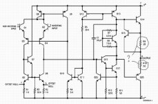
I see very strange results. Output node voltages are 3V on left hand side and 13v on right hand side (differential 10V). The other channel shows the same results. I have struggled about 12 hours to solve the problem, but in vain. I have measured output node voltages of LM741, -11V and -11V (differential almost 0V). The other channel shows the same results. I have looked back into the schematic diagram of LM741 (attached below) and found the different Emitter resistor values of R9 and R10. I smell.
I suspect one of three: (1) Being confused with the leg number reading of top view or bottom view, I might have soldered LM741 incorrect; (2) I might have taken a stupid selection of LM741 without consideration of the different R9 and R10; or, (3) I might have been drunk for the last 12 hours. Would you please kindly help me?
JH
PS. Congratulation!!! Netlist.
I see very strange results. Output node voltages are 3V on left hand side and 13v on right hand side (differential 10V). The other channel shows the same results. I have struggled about 12 hours to solve the problem, but in vain.
I have measured output node voltages of LM741, -11V and -11V (differential almost 0V). The other channel shows the same results. I have looked back into the schematic diagram of LM741 (attached below) and found the different Emitter resistor values of R9 and R10. I smell. I suspect one of three: (1) Being confused with the leg number reading of top view or bottom view, I might have soldered LM741 incorrect; (2) I might have taken a stupid selection of LM741 without consideration of the different R9 and R10; or, (3) I might have been drunk for the last 12 hours. Would you please kindly help me?
JH
PS. Congratulation!!! Netlist.
Attachments
I suspect one of three: (1) Being confused with the leg number reading of top view or bottom view, I might have soldered LM741 incorrect; (2) I might have taken a stupid selection of LM741 without consideration of the different R9 and R10; or, (3) I might have been drunk for the last 12 hours. Would you please kindly help me?
I told you, 741 output stage sucks

That reminds me on my one and only Amp that I built ever.
 741 metal can and dip packages have different pinouts. 😡
 There was only smoke in my lab, but I was 11 or 12 of age and did not know...
Now I am planning to built my second amp, and this will be a very good one 😎
Hi, JH
Don't get dissapointed
When you take the 741 in bottom view, pin 1 is the first pin after
the small lid. Then you count clockwise, so pin 8 is the small lid.
The so called 'stupid selection' is not an option. It should work at least a bit, maybe not perfect.
The third option can't be, since drinking coffee...
Check your pin's and let us know!!

I assume we are only talking about the metal can package, because JH used those as seen on his pictures.
The PDF at National shows the top view and that is confusing if you don't know it's the top view.
But indeed the dip-package is very different 😉
/Hugo - Will request all manufacturers to label their pins from now on
The PDF at National shows the top view and that is confusing if you don't know it's the top view.
But indeed the dip-package is very different 😉
/Hugo - Will request all manufacturers to label their pins from now on
JH,
You have other opamps around?
Maybe Bernhard and others here are right about the 741.
No mather how I try, I can't make the circuit work (on a sim)
with the 741
So, I'm not saying it's not possible,I don't have 741's at hand.
Can't you buy an lm6181 over there?
And a couple of MJE15030/31?
/Hugo
You have other opamps around?
Maybe Bernhard and others here are right about the 741.
No mather how I try, I can't make the circuit work (on a sim)
with the 741
So, I'm not saying it's not possible,I don't have 741's at hand.
Can't you buy an lm6181 over there?
And a couple of MJE15030/31?
/Hugo
 What about paralleling OPs, I mean 200 or so...
I have lots of TL082, ten by ten would be 200 OPs, if one can drive 1 kohm, 200 can drive 5 ohm.
Paralleling decreases noise, what about distortion ?

For those about to drill
Bernhard, have a look here : http://headwize2.powerpill.org/projects/showproj.php?file=meier3_prj.htm .
This dude uses 44 opamps per channel working in class A which comes out to 2000 holes to drill and solder.
At least you can save the money for the heatsinks.
A nice idea but I still wonder it works with those high-speed devices.
Bernhard said:
Send them over, I'll try...
Configure those TL's in an X-circuit, I bet the distortion will be
eliminated.
Just kidding
/Hugo
This 44-OP-amp looks interesting, but i found my TL082 are not good, because they have large-value-resistors in the rails of the output devices and also one on the output itself.
This will also be an issue with the design that is discussed in this thread.
Every type of OP will need different values of the external resistors, I guess.
This will also be an issue with the design that is discussed in this thread.
Every type of OP will need different values of the external resistors, I guess.
I missed that. It will definitely work better with that output not grounded. Interestingly, SuperSymmetry amps do work with one output grounded, in fact that's the best way to run one used as a preamp with a single-ended output.Bernhard said:Ok, I was mainly concerned about the output, of which one side is grounded 🙁
Ok, so if one output is grounded we have close to 15Vpp and if not grounded, 30Vpp ? Error ?
Any recommendations for a high current & low cost OP to try this parallel OP circuit ?
Any recommendations for a high current & low cost OP to try this parallel OP circuit ?
Nelson Pass said:
I missed that. It will definitely work better with that output not grounded. Interestingly, SuperSymmetry amps do work with one output grounded, in fact that's the best way to run one used as a preamp with a single-ended output.
Well, in that case, there's something wrong my circuit. It plays really very good with I connect one output to ground. Almost 20Vpp with 1Khz sinewave on the scope. Very clean sound. Look at the schematic on post #157. The moment I disconnect that ground, the gain is completely gone. Then with R5, R6, R7, R8 which are trimmers I can make it work at max half the power.
Another funny thing is that when I connect the ground of my scope at that (not grounded output), everything is back to normal.
Again 20Vpp on the scope
I overlooked everything carefully this afternoon, also thinking that output shouldn't be grounded, but found nothing wrong.
/Hugo – not happy now with that grounded sound 🙂
- Status
- Not open for further replies.
- Home
- Amplifiers
- Pass Labs
- Monolithic SuperSymmetry with Current Feedback