Thanks, Netlist. I have soldered the can type LM741 correctly from the beginning--clockwise leg numbering on bottom view. I have experimented R5-R8 with variations from 2k to 100k. Nevertheless, the results are almost same without any improvement. In addition, I have changed with different grounded resistor values from the OP input terminals, in vain. I am thinking more and more that LM741 is not practically suitable for the circuit. I might need to use other OPs (e.g. LM6181 size) and transistors or fets having greater dc gain. Problem is I do not know where I can get these nearby. Brrrrrrrrrr...
JH
JH
jh6you said:Problem is I do not know where I can get these nearby. Brrrrrrrrrr...
JH
http://www.leocom.co.kr/ ?
/Hugo
Msscf
I think the amp works with the right side output grounded only because the right side input is also grounded. If this was not the case, it might still work, but you would run a lot of useless current into the ground.
But this is a neat little circuit, well done Netlist.
BTW, it may even work better with R19 reduced, you probably can get away with 10 Ohms or so. What you want is as low as possible output swing on the opamp output to optimise the current conversion.
As for the choice of opamps, one factor to check for would be that the opamp should ideally have a very low, or at least constant, quiescent current. You want all the signal current coming out of the output to be reflected as accurately as possible on the supply terminals.
Jan Didden
Netlist said:
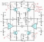
Well, in that case, there's something wrong my circuit. It plays really very good with I connect one output to ground. Almost 20Vpp with 1Khz sinewave on the scope. Very clean sound. Look at the schematic on post #157. The moment I disconnect that ground, the gain is completely gone. Then with R5, R6, R7, R8 which are trimmers I can make it work at max half the power.
Another funny thing is that when I connect the ground of my scope at that (not grounded output), everything is back to normal.
Again 20Vpp on the scope
I overlooked everything carefully this afternoon, also thinking that output shouldn't be grounded, but found nothing wrong.
/Hugo – not happy now with that grounded sound 🙂
I think the amp works with the right side output grounded only because the right side input is also grounded. If this was not the case, it might still work, but you would run a lot of useless current into the ground.
But this is a neat little circuit, well done Netlist.
BTW, it may even work better with R19 reduced, you probably can get away with 10 Ohms or so. What you want is as low as possible output swing on the opamp output to optimise the current conversion.
As for the choice of opamps, one factor to check for would be that the opamp should ideally have a very low, or at least constant, quiescent current. You want all the signal current coming out of the output to be reflected as accurately as possible on the supply terminals.
Jan Didden
Hi Netlist
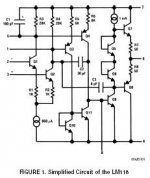
Impressed, impressed. You know better than me about Korean dealer. Thanks for the info. I would contact the dealer later. Tonight I will replace LM741 with LM118, and will see again what happens. The simplified schematic diagram of LM118 calls my interest even though it has a low maximum output current capacity. I will inform you about the result.
JH
Attachments
Re: Msscf
I now run the amp balanced, but same problem; I still have to connect the one output to groung to have the full gain. Reduced R0 to 10ohm with increased gain as a result.
Carry on, JH, i'm sure you will have results. I'll try the LM118 on the sim in the meantime.
/Hugo
Thanks Janjanneman said:
I think the amp works with the right side output grounded only because the right side input is also grounded.
Jan Didden
I now run the amp balanced, but same problem; I still have to connect the one output to groung to have the full gain. Reduced R0 to 10ohm with increased gain as a result.
jh6you said:Hi Netlist
Tonight I will replace LM741 with LM118, and will see again what happens.
JH
Carry on, JH, i'm sure you will have results. I'll try the LM118 on the sim in the meantime.
/Hugo
Msscf
Hmm. Do you say you drive the right hand input and you STILL must ground the right hand side of the load for gain? Sounds like a circuit error, as if Q10-Q12 isn't sinking/sourcing any current. If you scope the opamp supply pins (right side) do you see any drive signal to the output stage (will be heavily distorted, so compare with what you see at the left hand side)?
Jan Didden
Edit: What's the quiescent voltage across the emitter resistors R13, 14, 15, 16?
LM118 seems to get me back to the working circuit.
I however still meet a problem. I have got output node voltages of all about 9V with no input signal. They should have been near to 0V...!?!? Thinking of the values strange, I have measured voltages at the inverting input terminals. O my... the node voltages are all about 1.3V. They should have been 0V too.
What is wrong...!?!? What am I forgetting...!?!?
sigh...
JH
PS. Welcome back Fred Dieckmann.
Msscf
Guys, guys,
You cannot just put in any opamp and think it'll be OK, got to do some thinking first!
The 118 (which is almost as old as thge 741 btw) has a bipolar front end, meaning there is current going in/out of the input terminals. With 10k on those inputs, of course you are getting input offset. Get a fet input opamp, or get rid of those obscenely large input resistors.
Secondly, don't forget that the quiescent current of the opamp sets up the bias current in the output stage. An opamp with 1 or 2 mA quiescent current will not class-AB bias the output stage with 150 ohms. Check the quiescent current of the opamp, calculate how much resistance you need to get to .65 volts or thereabouts and put that resistor in. Then re-check the actual bias current by measuring the voltage drop on the output stage emitter resistors.
Jan Didden
PS Since a low quiescent current opamp will allow a larger base resistor, that will increase the gain and make the whole amp more linear. Another option would be to put a driver transistor in. I mean, in a conventional amp you would also not drive the output stage directly by the Vas stage without a couple of drivers.
Hi, Jan
Still referring to drawing post #157
R19: 220ohm
All measurements done without grounded output.
All Opamp supply pins show output.
Base Q10: 23mVpp
Base Q12: 80mVpp
Base Q11: 125mVpp
Base Q9: 60mVpp
Quiescent voltage across
R13: 400mV (DC)
R14: 310mV
R15: 170mV
R16: 260mV
All resistors 0.94 ohm
Input: 3.2Vpp balanced
Output: 7.5Vpp with 8ohm speaker
Power consumption: 760mA both +/-15V, so total is 1.52A
Setting of the trimmers are now optimal.
********************************
With output grounded:
All Opamp supply pins show output.
Base Q10: 1.8Vpp
Base Q12: 0.5Vpp
Base Q11: 1.1Vpp
Base Q9: 1Vpp
All very distorted, half sinewaves or worse.
Quiescent voltage across
R13: 520mV (DC)
R14: 500mV
R15: 90mV
R16: 770mV
Output: 15Vpp with 8ohm speaker
Power consumption: 1.38A -15V, 730mA +15V
/Hugo - the more he plays with the circuit, the nastier it gets
MSSCF
OK, let's get this show on the road....
There is probably something amiss with the DC balance conditions.
Try this:
- change R17, 18, 11, 12 to 1k;
-Leave off R1, 2 and the signal source. Leave both inputs unconncted. Use a light load say 100 ohms.
- Change R3, 4 to 4.7k to give you a about times 5 gain.
- Now check the voltage across R13, 14, 15, 16.
Let's go for 100mA quiescent current, so you want 100mV across these resistors. Adjust R5, 6, 7, 8 to get there. When that is done, your outputs should be very close to zero.
I still think you need drivers. Note that the ONLY mechanism to couple the two halves is through R19, which is too large anyway.
How does this work: assume that the left hand input goes up. The opamp output wants to go down. For that it needs to bleed current from the opamp output through R6. This will increase the current through Q9, lowering the left hand output voltage. Now the same current pulled out of the left opamp output is pulled out of the right hand opamp output. Thus the right hand opamp output (I see, you call it X3. ok). So X3 pulls this current through R7, increasing Q12 current and upping the right hand output. All well and good, but is the transistors left and right (and up and down) are not matched, this whole process is not linear or balanced, hence the distortion. Now feedback would take care of that, IF the opamp outputs were hard grounded, and the thing was single ended.
Jan Didden
Re: MSSCF
Highly appreciated, Jan
I will re-read this and others comments till I fully understand and give it a try tomorrow.
It's still a mystery why, when I ground that output, and trim the amp, it plays very well but I won't bother too much about that anymore;
/Hugo - Likes people who can explain complicated things in a simple way 😉
janneman said:OK, let's get this show on the road....
Jan Didden
Highly appreciated, Jan
I will re-read this and others comments till I fully understand and give it a try tomorrow.
It's still a mystery why, when I ground that output, and trim the amp, it plays very well
but I won't bother too much about that anymore;/Hugo - Likes people who can explain complicated things in a simple way 😉
Bernhard said:So I have started building that circuit too... Very close to the fire-extinguisher
Fine, wich components?
/Hugo
MJ14002/3 and NE5532, stuff from my grab bags.
MJ14003 *Motorola Preferred Device 60 AMPERES COMPLEMENTARY
SILICON POWER TRANSITORS 60+80 VOLTS 300 WATTS
Re: Re: Msscf
Are you connecting the load across the two outputs, or are you
running it from one output to ground?
Netlist said:I now run the amp balanced, but same problem; I still have to connect the one output to groung to have the full gain
Are you connecting the load across the two outputs, or are you
running it from one output to ground?
Bernhard said:MJ14002/3 and NE5532, stuff from my grab bags.
Nice, but as Nelson and Jan are (almost) our only "smart" guys,
read what they learned us! 😉
/hugo - couldn't live without thinkers 😎
Re: Re: Re: Msscf
I connect the speaker across the two outputs, with almost no gain.
When I connect the left hand output to ground (speaker remains where he is) the full (?) power reveals! Ref. Post #157
/Hugo
BTW Congrats with your new job
I just connected the speaker between the left hand output
and ground and it works well also. So, it doesn't matter if I connect the right hand output to ground, or the 1 speaker terminal to ground, both ways work.
Nelson Pass said:
Are you connecting the load across the two outputs, or are you
running it from one output to ground?
I connect the speaker across the two outputs, with almost no gain.
When I connect the left hand output to ground (speaker remains where he is) the full (?) power reveals! Ref. Post #157
/Hugo
BTW Congrats with your new job
I just connected the speaker between the left hand output
and ground and it works well also. So, it doesn't matter if I connect the right hand output to ground, or the 1 speaker terminal to ground, both ways work.
Nelson Pass said:Are you measuring your output across the load, instead of
from one output to ground?
OK, lets say I connect the load between the left
and right hand output. Just as it should be, no grounding.
I then measure with the scope, probe attached to left hand output. Probe-ground to ground.
Almost no output comes out of the speaker.
Very funny thing happens now, when I connect the probe-ground to right hand output, or I ground that output, the sound appears.
Same thing happens (just discovered) when I connect my probe
to the right hand output. Almost no output. Connecting the probe-ground to the left hand output or grounding that output brings back the sound, but with less gain then in first configuration.
/Hugo - can't explain any better 😉
- Status
- Not open for further replies.
- Home
- Amplifiers
- Pass Labs
- Monolithic SuperSymmetry with Current Feedback