JH,
I could be wrong but I think the 1 ohm resistor in the Zobel network needs to be changed to 10 ohms.
You could also attach an adjustable current source from each B+ pin of each ic to ground to set the bias on the output transistors and adjust offset.
Jam
I could be wrong but I think the 1 ohm resistor in the Zobel network needs to be changed to 10 ohms.
You could also attach an adjustable current source from each B+ pin of each ic to ground to set the bias on the output transistors and adjust offset.
Jam
jh6you said:If this test version has no hope, please tell me so. I would much appreciate it.
Just be prepare to adjust every value. I suggest that you
use trim pots everywhere the first time around, and put some
.47 or 1 ohm Emitter resistors on the outputs first time.
Thinking about it, if I were you, first time around I would
also put 1K ohms from each (-) input to ground on the op amps.
also put 1K ohms from each (-) input to ground on the op amps.
Nelson Pass said:
Just be prepare to adjust every value.
Thanks for the comment. ¡°Just prepare to adjust every value¡± means no, no, no in business language. Accordingly, I tried another revision.
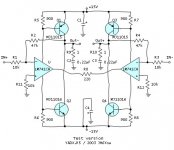
MJ11015 and MJ11016 seem to have too high dc current gains (>1000), and R5-8 values might be dubious. I want to replace these. I choose new transistors of MJ4502 and MJ802 having dc current gain of 25-100. Reflecting LM741CN having the supply current of 1.7mA-2.8mA, I take R5-R8 of 2k, expecting the idling dc current in between 40mA and 250mA through the output transistors. By the way, the most difficult requirement seems the trim pots everywhere...
Jam, where is the "each B+ pin of each ic?"
JH
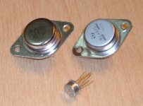
PS. Tomorrow, I will post picture of LM741CH, MJ4502 and MJ802.
Attachments

Final circuit?
Hi JH,
We are all settled in with a glass of good beer.
Now please rig up the circuit and tell us what happens !
Remember to do what Nelson said. Take each -ve input to ground through a 1K resistor - do not leave it open to start with.
Do you have a scope? I sure hope so.
Cheers.
Hi JH,
We are all settled in with a glass of good beer.
Now please rig up the circuit and tell us what happens !
Remember to do what Nelson said. Take each -ve input to ground through a 1K resistor - do not leave it open to start with.
Do you have a scope? I sure hope so.
Cheers.
Looks pretty good. Now be prepared for the drift in absolute DC on the outputs, just like any X amp. Look through some of the postings on the Aleph X thread for a solution.
ashok said:Thanks Nelson.
I did not buy the printer port as I was trying to decide if the other version which came with FFT software was worth it. Actually maybe only the printer port is worth it.
I could never find a users review of the Wavestar software for the TDS.
Ashok,
Tektronix includes a 30 day trial version of the Wavestar software with the RS232 module (TDS2CMA). If you like writing your own programs, the TDS2CMA module gives you that capability. That is the approach I am taking since I don't need many of the features available in Wavestar.
Attachments


I am concerned about the drift in absolute DC on the outputs. If I use a fixed R5 of 2k and pots for R6, R7 and R8, could I tackle the potential drift problem? Or another way is better...? I am wondering... Please your advice, please.
JH
JH
JH
I like your struggle with the XCard very much.
It´s some hard job, I wish all the best I can think of for you.
You know, I am a SIMetrix-man, so obvious I had to make a sim of your circiut.
How ever, I felt during my sims, that it might be a good idea to get each half of the circiut running before connecting them to the X configuration, and just take 1K from opampoutput to ground to get some current flowing through the BJT´s while you do.
I rearley hope you wil manege to make it.
Go ahed, do it!

I suggest you start by loading each output to ground through 100 ohms or so. This will add some stability to the absolute DC drift so that when you make the other adjustments it will tend to stay put.jh6you said:I am concerned about the drift in absolute DC on the outputs. If I use a fixed R5 of 2k and pots for R6, R7 and R8, could I tackle the potential drift problem? Or another way is better...?
My first design: 
Could that work ?
For the name of that creation please refer to the picture.

In case that it could work:
May be the feedback should be on each same side ?
Is feedback necessary at all ?
He he, the tubes in my plasma tweeters got some pale blue glow all over the middle area when it is real dark in my listening room, anything to worry about ? 😱
Could that work ?
For the name of that creation
please refer to the picture.
In case that it could work:
May be the feedback should be on each same side ?
Is feedback necessary at all ?
He he, the tubes in my plasma tweeters got some pale blue glow all over the middle area when it is real dark in my listening room, anything to worry about ? 😱
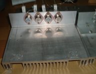
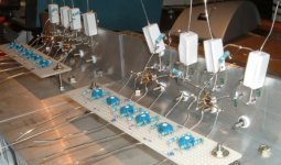
Progress 3
Thanks to your encouragement and advice, it goes well even if the speed is somewhat slow. Soldering the components, I have thought about two things: The 1k from the inverting input to the ground might be for small input current, and the 10K from the output to the ground might be for a kind of "equilibrium of complementary" and so for the dc drift stability. Is the equilibrium of complementary proper expression, Mr Nelson Pass?
This weekend, I will get a 300VA transformer of 2 x 12V secondary...
JH
Attachments
- Status
- Not open for further replies.
- Home
- Amplifiers
- Pass Labs
- Monolithic SuperSymmetry with Current Feedback