@SRMcGee: I think it makes more sense to ask posters to include a photo in the post where the template or file is posted. The master post and tables are intended to act as a finding tool to quickly allow individuals to narrow down their search, and then jump to the individual post to see if what is described actually meets their needs.
I finished a Modulus-86 Rev 3 last week, in a Modushop Dissipante 2U 300mm chassis (10mm front, 3mm covers): https://www.diyaudio.com/community/threads/modulus-86-build-thread.267802/page-311#post-7555555
I had to learn QCAD to be able to do this. Modushop has been very kind and helpful in getting my drawings up to spec.
See the attachments in this post for my drawings. There are five files. Three versions of the CAD drawing (DXF files), and an EPS file that is used for printing, I created it by importing a DXF into Affinity Designer, than exporting to EPS.
Please be advised that the hole for the IEC inlet (Furutech) is a bit too large in my drawings. I initially planned to order another part, which was out of stock. I forgot to edit the drawing for the Furutech part. It's best to customize dimensions for your own specific parts. If you use Neutrik sockets like I did, their XLR, RCA and Speakon sockets all fit the same dimensions.
My drawings are based of the plain drawings from Modushop that you can request. I made a separate file where I draw the outlines for all parts I use, then I copy those to the chassis drawing.
If you use my drawings, please read the post I referenced too. It contains my lessons learned and where I cut it close with some design tolerances. You might want to make slight adjustments.
Learning QCAD was a significant hurdle for me. If you are into building custom chassis though, I can highly recommend learning at least the basics with one or two tutorials. The learning process for this visual stuff also probably comes easier to most people, I'm bad with anything graphical.
I had to learn QCAD to be able to do this. Modushop has been very kind and helpful in getting my drawings up to spec.
See the attachments in this post for my drawings. There are five files. Three versions of the CAD drawing (DXF files), and an EPS file that is used for printing, I created it by importing a DXF into Affinity Designer, than exporting to EPS.
- Dissipante 2U 300mm 10mm 3mm Modulus-86 rev 3.0 - full info - v2.dxf --> This is my own working file that contains my guidelines and measurements and everything else. I export from this file the two next files
- Dissipante 2U 300mm 10mm 3mm Modulus-86 rev 3.0 - full details - v2.dxf --> This is the first file I send to Modushop, still full details but with some of my own layers removed, keeping only production-relevant details. Please note that in this instance, my full details file contains changes not made in the full info file. I messed this up
- Dissipante 2U 300mm 10mm 3mm Modulus-86 rev 3.0 - drilling info - v2.dxf --> This is the second file I send to Modushop, it contains only info relevant for drilling and threading
- Dissipante 2U 300mm 10mm 3mm Modulus-86 rev 3.0 - printing info - v2.dxf --> This is a file containing only the relevant info for printing (Modushop likes to have the hole outlines too, they assist in aligning the prints). I use this file to generate an EPS file from that Modushop needs for printing
- Dissipante 2U 300mm 10mm 3mm Modulus-86 rev 3.0 - printing info - v2.eps --> This is the third file I send to Modushop. This is the EPS file that I generated from the DXF with Affinity Photo. Modushop uses this file for printing
Please be advised that the hole for the IEC inlet (Furutech) is a bit too large in my drawings. I initially planned to order another part, which was out of stock. I forgot to edit the drawing for the Furutech part. It's best to customize dimensions for your own specific parts. If you use Neutrik sockets like I did, their XLR, RCA and Speakon sockets all fit the same dimensions.
My drawings are based of the plain drawings from Modushop that you can request. I made a separate file where I draw the outlines for all parts I use, then I copy those to the chassis drawing.
If you use my drawings, please read the post I referenced too. It contains my lessons learned and where I cut it close with some design tolerances. You might want to make slight adjustments.
Learning QCAD was a significant hurdle for me. If you are into building custom chassis though, I can highly recommend learning at least the basics with one or two tutorials. The learning process for this visual stuff also probably comes easier to most people, I'm bad with anything graphical.
Last edited:
I should have made it clear that I am not affiliated with Neurochrome. It wasn't nice of me to distribute the Neurochrome logo like this. I've attached new drawings without the logo's to this post. Should anyone wish to add the Neurochrome logo to their build, I'm positive Tom would accommodate. I'll ask a mod to remove the attached drawings from the previous post.
Attachments

Hi.
I don't know what's really possible informatically speaking but i think that, for the ease of "1st access", it would be better to have a "Full Box Assembly" on top of the hierarchy, then leading to Library 1 and 2.
So people could imagine the overall assembly, know everything exist and later might change 1 component for another. People new to box design would just pick up something existing, people comfortable would pick up 1 design, change a front panel (or else) for another one and so on.
Like
Library 0 "Top Assembly"
|
- Library 1 "Individual Components"
|
- Library 2 "Individual Features to make individual components"
1 thing: could this kind of database/table/... be implemented within the DIY Audio forum (centralized place, high visibility, ...) or not and another solution has to be found ?
Have a nice day
What is a "Library 0 "Top Assembly"? Is this your name for a "Full Box Assembly"? If this is intended to include both front and back panel, I think that it would be better to simply include the notation within the table under the name of the chassis. Each person ultimately will have to review candidate drawings based upon the table's description, select what is needed, and copy over the drawing file and submit them to their fabricator of choice (e.g., Mod-U-Shop, Par-Metal).
As far as another place within DIY Audio to implement this idea, let me reach out to DIY Audio to ask them what might be available, if any.
As far as another place within DIY Audio to implement this idea, let me reach out to DIY Audio to ask them what might be available, if any.
I don't think it's possible to have a directory structure within DIY Audio. What could be done, however, is that @Halauhula updates Post #1 to include an index/list of posts that contain drawings. The list could just be chronological or it could be grouped into "Individual Components" and "Full Chassis Designs" (or whatever). OP is the only one aside from moderators who has the ability to edit Post #1. But, of course, keeping the list updated takes work...
Tom
Tom
Tom: you are correct; it will take work. Based upon what Iʻm seeing in individual threads and posts, there does not seem to be many individuals creating dog for machining front and back panels; accordingly I am hoping there will not be too much work in updating Post #1 to add new drawings and links as they are made available.
Do you have any comments on the table structure in Post 18?
Do you have any comments on the table structure in Post 18?
Hi
A] "What is a "Library 0 "Top Assembly"? Is this your name for a "Full Box Assembly"?" Yes, it is!
B] I am personnaly OK with @tomchr on "updates Post #1 to include an index/list of posts that contain drawings", but it does requires to have a maintainer, but maybe the easiest solution to start building something simple
Or a link to a Google Sheet shared with anybody?
C] With "something simple":
i guess the table should only by text/links pointing to the post on which the user put pictures of the full box assembly / components & related files. Like one would post in "Show your PASS Amp" or somewhere else, then table shall be updated.
D] Ok with any format
Have a nice day
Hi
// not exactly Modushop punch library but... maybe useful to some //
I don't know if things could be put in place to have a sort of database for chassis template / example.
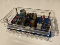
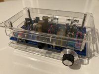
In any case, maybe to have this thread as a repository, here are files for a very simple "laser cut & bended plexiglass cover" for Pete Millett NuTube Hybrid headphone amp
1. Electronic project here http://www.pmillett.com/nuhybrid.html
2. Fusion original files "NuTube-Folded-Box v11_PMillett"
3. Derivatives (dxf, step, Fusion pictures) "NuTube_DXF_4PMillett" "NuTube-Folded-Box v11_PMillett" "NuTube-Box-..."
4. Pictures of the finished device "NuTube-Headphone-Plexi-ISO-Front" "NuTube-Headphone-Plexi-ISO-Back"
// not exactly Modushop punch library but... maybe useful to some //
I don't know if things could be put in place to have a sort of database for chassis template / example.
In any case, maybe to have this thread as a repository, here are files for a very simple "laser cut & bended plexiglass cover" for Pete Millett NuTube Hybrid headphone amp
1. Electronic project here http://www.pmillett.com/nuhybrid.html
2. Fusion original files "NuTube-Folded-Box v11_PMillett"
3. Derivatives (dxf, step, Fusion pictures) "NuTube_DXF_4PMillett" "NuTube-Folded-Box v11_PMillett" "NuTube-Box-..."
4. Pictures of the finished device "NuTube-Headphone-Plexi-ISO-Front" "NuTube-Headphone-Plexi-ISO-Back"
Attachments
-
 NuTube-Headphone-Plexi-ISO-Back.jpg329.9 KB · Views: 92
 -
 NuTube-Headphone-Plexi-ISO-Front.jpg320.6 KB · Views: 87
 -
NuTube-Folded-Box v11_PMillett.step92.8 KB · Views: 61
-
 NuTube-Box-Flat.jpg44.6 KB · Views: 80
 -
 NuTube-Box-Iso.jpg40.1 KB · Views: 86
 -
NuTube_DXF_4PMillett.zip852 bytes · Views: 57
-
NuTube-Folded-Box v11_PMillett.zip126.7 KB · Views: 54
-
NuTube-Folded-Box v12 Flat.step92.8 KB · Views: 50
Last edited:
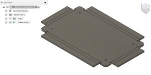
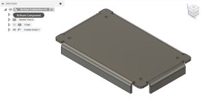
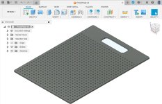
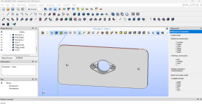
A set of files for a "prototype plate": a laser cut plate mimicking the perforated plate in a "Mini Dissipante", so i could place components easily before ordering the actual plate from Modushop. I put a hole serving as a "handle" for ease of transportation between different places i do stuff.
Fusion file, Dxf, Step and a picture of the file in Fusion
Picture of the real use here https://www.diyaudio.com/community/...amplifier-modules.383745/page-19#post-7495374
Fusion file, Dxf, Step and a picture of the file in Fusion
Picture of the real use here https://www.diyaudio.com/community/...amplifier-modules.383745/page-19#post-7495374
Attachments
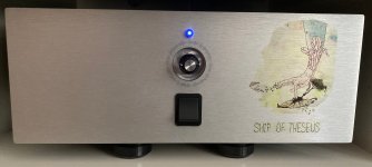
Mini-Dissipante 300mm for an integrated amp (but only 1 input, no switch): Front End 2022 + Ship of Theseus: Front Panel Design files.
*Front panel has a squarish hole for a big switch, hole for volume potentiometer & LED.
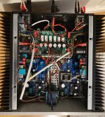
*Rear Panel has XLR inputs, loudspeaker outputs, some holes for RCA.
*Hole for power is bigger than necessary for this build = Some modularity for a later First Watt with linear PSU and IEC (instead of the Thesus PSU connection): archive Adaptation-IEC-Theseus-PSU with HDF, STP and STL file (hdf is editable in "Salome platform" Salome 3D Link)
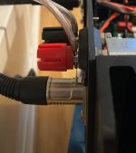
*Issue on the rear panel: louspeaker & XLR connectors should be farther away (see pics)
*Pic for quick assessment, more here DIY audio Link
This is for anybody to use & modify.
*Front panel has a squarish hole for a big switch, hole for volume potentiometer & LED.
*Rear Panel has XLR inputs, loudspeaker outputs, some holes for RCA.
*Hole for power is bigger than necessary for this build = Some modularity for a later First Watt with linear PSU and IEC (instead of the Thesus PSU connection): archive Adaptation-IEC-Theseus-PSU with HDF, STP and STL file (hdf is editable in "Salome platform" Salome 3D Link)
*Issue on the rear panel: louspeaker & XLR connectors should be farther away (see pics)
*Pic for quick assessment, more here DIY audio Link
This is for anybody to use & modify.
Attachments
-
Adaptation-IEC-Theseus-PSU.zip604.8 KB · Views: 30
-
ShipOfTheseus-FrontPanelDesign.zip1.4 MB · Views: 39
-
 Ship_of_Theseus_FrontPanel.jpg294.8 KB · Views: 54
 -
 Ship_of_Theseus_InternalTop.jpg774 KB · Views: 51
 -
 Ship_of_Theseus_InXLR_OutSpkr.jpg440.9 KB · Views: 54
 -
 Adaptation-IEC-TheseusPSU-1.png117.5 KB · Views: 51
- Home
- Design & Build
- Parts
- Modushop chassis punch design library