I don't see a problem with lashing "n" single-channel units to your heat sink if you want an "n" channel amp, even if n=2.
Is Modulus-86 working fine with SMPS (i.e. no significant performance degradation)?
Yep. I've measured the MOD86 on a Connex SMPS300RE. It performs as well on the SMPS as it does on a linear supply.
Tom
I don't see a problem with lashing "n" single-channel units to your heat sink if you want an "n" channel amp, even if n=2.
I don't either. As long as the heat sink can dissipate the heat of all the channels.
Mark's suggestion of adding a temperature sensor is a good one. The TO-220 from Microchip is pretty neat. It sure makes the mechanical side of things easy.
Tom
I've measured the MOD86 on a Connex SMPS300RE. It performs as well on the SMPS as it does on a linear supply.
What voltage you use with the Connex SMPS300RE: +/- 24V, +/- 30V or custom?
I'm mulling over building a stereo board as I have a customer/co-conspirator who's looking for a multi-channel amp. I'm leaning in the direction of a stereo amp board that allows for stacking. You could then stack as many stereo boards as you can pack in on your heat sink.
Tom
For stereo board design, would it be greate if one design can allow both two channel mode and BTL/parallel mode? This will make the board more versatile - e.g. more channels at lower power or less channel at higher power.
For stereo board design, would it be greate if one design can allow both two channel mode and BTL/parallel mode? This will make the board more versatile - e.g. more channels at lower power or less channel at higher power.
Sadly, the 7 A current limit of the LM3886 isn't enough to allow for BTL with anything but 8 Ω loads.
Tom
... (snip) ...
And about patents? You can even patent the word "Monster" (Google for it)
... (snip) ...
It's worthwhile to point out that a "patent" for the word "Monster" is simply a pecularity of the United States Patent and Trade Mark Office (USPTO) where they refer to almost all registerable Intellectual Property as a "patent".
It causes confusion, as a true Patent (unique, non-obvious idea) is one thing, and various forms of IP are another.
In every other country on Earth, they refer to patents as Patents, and then to other IP by other terms ... for example a Registered Trade Mark (versus a "patent" on "Monster") or Registered Industrial Design (versus a USPTO "Design Patent" such as the one that describes the shape of the Q-Ray Bracelet).
Last edited:
why not LME49990
As Bill said: It has been discontinued by TI. I can't justify hinging my business on obsolete parts. It would have been a nice candidate otherwise, assuming it's well-behaved in the gain/phase plot (not included in the data sheet).
The LME49710HA or LME49720MA are the best candidates to date. There's also a family member in the LMP-series that could be interesting. It's specified very, very closely like an LME49710. However, it is SMD only.
The world may just have to live with SMD components. Such is life.
Tom
These measurements on first sight look nice, but how about a frequency plot out to 10MHz?
I do apologize for the delayed response here. I had to dig myself out from under a couple of exams and paid gigs so my lab time was limited. I also wanted to make sure I allotted enough time to do a thorough job as concerns about stability are always to be taken seriously.
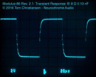
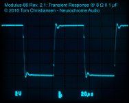
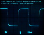
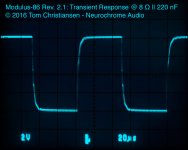
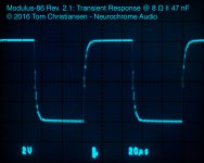
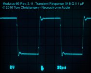
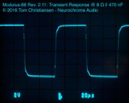
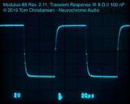
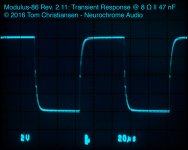
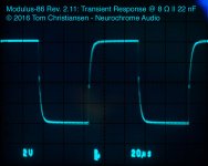
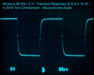
I am attaching a stack of transient response plots for the MOD86 Rev. 2.1. The plots were done with various load capacitance in parallel with the 8 Ω load resistor. The loop is stable.
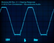
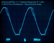
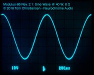
Also attached is a scope shot showing the clipping response at 100 Hz, which is quite clean, and the clipping response at 1 kHz, which does show a little bit of buzz as the amp recovers from clipping. Most importantly, the artifacts from the loop dynamics (LM3886 gain change) are very short term and the amp quickly gets back to normal.
I have torture tested this amplifier to great lengths and I am fully confident in its abilities as an high-end audio amplifier. That said, it is designed to operate away from clipping. It is not a guitar amplifier.
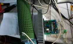
In terms of actual, practical use, my 4-channel MOD86 Rev. 2.0 amp is still going strong. It sees hours of use every day and I do crank the music on occasion. It drives my LXmini speakers as well today as it did nearly a year ago when I built it. Life is good. 🙂
Tom
Attachments
-
 MOD86_R2p1_Transient_8R10nF.jpg111.6 KB · Views: 580
 -
 MOD86_R2p1_Transient_8R1uF.jpg108.3 KB · Views: 136
 -
 MOD86_R2p1_Transient_8R470nF.jpg112.1 KB · Views: 133
 -
 MOD86_R2p1_Transient_8R220nF.jpg111.8 KB · Views: 569
 -
 MOD86_R2p1_Transient_8R100nF.jpg113.3 KB · Views: 575
 -
 MOD86_R2p1_Transient_8R47nF.jpg111.9 KB · Views: 579
 -
 MOD86_R2p1_Transient_8R22nF.jpg113.6 KB · Views: 575
 -
 MOD86_R2p1_Clipping.jpg195 KB · Views: 167
 -
 MOD86_R2p1_Clipping_1kHz.jpg122.9 KB · Views: 174
Last edited:
I reached the limit on the number of uploaded files, hence, I'm splitting my response in two.
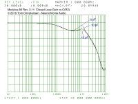
Now for the requested closed loop gain plot to 10 MHz. That is attached. It does show a hump at 1 MHz. This hump is due to the local feedback loop around the LM3886. I'll chalk it up to yet another quirk of the LM3886. It is likely due to the noise gain compensation (180 pF cap between the two inputs) recommended by National/TI.
If this hump bothers you, you can add 10 pF NP0/C0G dielectric across R2, the feedback resistor on the LM3886.
Personally, I see no need for any circuit changes, but each to his own. A 10 pF cap across R2 does reduce the hump and it also appears to clean up the edges on the transient response a bit. The downside is that it results in slightly worse clipping response, so you shave off a few watt of maximum output power (60 W rather than 65 W into 4 Ω). The clipping response isn't significantly different in terms of the overload/recovery behaviour, the amp just clips a touch sooner.
I retook the transient response plots with 10 pF added across R2. Don't read too much into the label "Rev. 2.11". I had to tell the setups apart somehow. 🙂
Tom
Attachments
-
 ClosedLoopGain_CR2_0-10-15pF.png33.2 KB · Views: 208
 -
 MOD86_R2p11_Transient_8R1uF.jpg107.1 KB · Views: 128
 -
 MOD86_R2p11_Transient_8R470nF.jpg112.3 KB · Views: 119
 -
 MOD86_R2p11_Transient_8R220nF.jpg116.3 KB · Views: 106
 -
 MOD86_R2p11_Transient_8R100nF.jpg115.7 KB · Views: 113
 -
 MOD86_R2p11_Transient_8R47nF.jpg108.2 KB · Views: 114
 -
 MOD86_R2p11_Transient_8R22nF.jpg114.2 KB · Views: 113
 -
 MOD86_R2p11_Transient_8R10nF.jpg110.4 KB · Views: 158
Last edited:
Do note that the input to the amp for the transient response measurements is a square wave with a very fast edge. The edge rate is 40 V/µs - about 37 times faster than the fastest edge rate possible for a rail-to-rail step in a 192 kHz sampling system (assuming 2 V RMS out).
As I said... Torture testing. 🙂
Tom
As I said... Torture testing. 🙂
Tom
You may find the 'buzz' is partly due to the SPIKE protection in LM3886.Also attached is a scope shot showing the clipping response at 100 Hz, which is quite clean, and the clipping response at 1 kHz, which does show a little bit of buzz as the amp recovers from clipping. Most importantly, the artifacts from the loop dynamics (LM3886 gain change) are very short term and the amp quickly gets back to normal.
If you repeat the test with eg 5V less rail voltages, you might find the 'buzz' disappears.
You may find the 'buzz' is partly due to the SPIKE protection in LM3886.
You know. That's pretty darn likely. At lower rail voltages the amp can clip a lot harder (almost to the point of a square wave) before the buzz starts. Also at no load, there's no buzz. Even at 16 Ω, there's no buzz. The SPiKe protection does indeed seem to have something to do with it.
Interesting quirk. I don't think there's any action for me to take, however.
Tom
There was a lot of hype about TIM in the 1970's. These days nobody talks about it any more, as it isn't very interesting (being a special case of SID) and because it is very easy to avoid altogether. Are you aware of the work on analyzing negative feedback by Bruno Putzeys and many other contemporary people (as opposed to stuff from 40 years ago)?
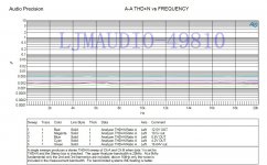
This is my LME49810 power amplifier.
After my test, 40 w THD + N = 0.002%.
The actual measurement data is bigger than the value in the IC official documentation PDF.
I think this is reasonable, because in the actual practice, many elements will bring some distortion.
Including capacitance, the power supply. Or the conductor. I don't believe anyone amplifier,
Can more than NS PDF document's data.
http://www.diyaudio.com/forums/chip-amps/290900-ljm-lme49810-ic-amp-2.html
Attachments

This is my LME49810 power amplifier.
After my test, 40 w THD + N = 0.002%.
Looks pretty good - but I thought you were talking about TIM (SID).
- Home
- Vendor's Bazaar
- Modulus-86: Composite amplifier achieving <0.0004 % THD+N.