However if you read Taming the LM3886 Chip Amplifier you will see that Tom has given away a lot to help those who wish to roll their own. The Mod-86 has always been a case of 'this is as about as far as you can go with this chip'. There are a few who could equal it, but most of us are not experienced enough at layout in order to be able to get close so buy the board.
Composite Amps are challenging to get right and very easy to get wrong!
Composite Amps are challenging to get right and very easy to get wrong!
I can't see the schematic in post1 nor in the link you have provided.
Block diagram is there. I have the schematic, but I can't share that. And the schematic is little use as the PCB is 50% of the performance.
In some previous posts, some say, tom charges to much.
He is a skilled engineer and to me his pricing is fair.
Have you ever lay out a PCB like this? - it takes a lot of work and time to get it right.
To much, is like the equipment they review on some high-end sites, most of the amps there cost $$$ and where do they come from.
Is a matching preamp in development to go with the Modulus-86 ?
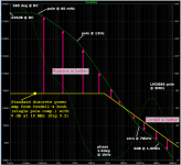
I've overlaid the open loop frequency response of a standard discrete-transistor power amplifier, from Bob Cordell's book p.174. It's in yellow; the modulus-86 is in green. Yellow is NOT a chip-amp, it's a dozen discrete transistors and some passive components, on a printed circuit board; Cordell's book goes into great detail.
Also attached is a distortion-vs-frequency plot of the LM3886 chip all by itself (i.e. not in a compound amplifier). Its weak zone is from 500Hz to 20kHz; in this region the Modulus-86 provides an extra ~30dB to ~0dB of gain for additional distortion reduction.
_
Also attached is a distortion-vs-frequency plot of the LM3886 chip all by itself (i.e. not in a compound amplifier). Its weak zone is from 500Hz to 20kHz; in this region the Modulus-86 provides an extra ~30dB to ~0dB of gain for additional distortion reduction.
_
Attachments
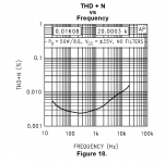
Here's the THD+N vs Frequency for the MOD86.
The MOD86 is a good 10x (20 dB) better than the naked LM3886 when it comes to THD+N. More importantly, the MOD86 offers much better PSRR, hence, performs as well on an unregulated supply as it does on a well-regulated lab supply. The performance of the naked LM3886 degrades significantly when it's fed by an unregulated supply. I showed the plot of MOD86 vs LM3886 earlier in the thread.
It's good to know that Cordell's amp is better outside the audio band, though... 😎
Tom
An externally hosted image should be here but it was not working when we last tested it.
The MOD86 is a good 10x (20 dB) better than the naked LM3886 when it comes to THD+N. More importantly, the MOD86 offers much better PSRR, hence, performs as well on an unregulated supply as it does on a well-regulated lab supply. The performance of the naked LM3886 degrades significantly when it's fed by an unregulated supply. I showed the plot of MOD86 vs LM3886 earlier in the thread.
It's good to know that Cordell's amp is better outside the audio band, though... 😎
Tom
Last edited:
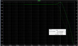
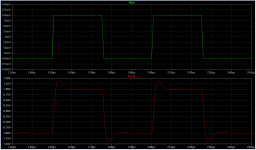
I connected the open loop transfer function plotted in #1392 above, to a feedback network that gave a closed loop gain of 10X (+20dB), just like the Modulus-86. The resulting closed loop amplifier had about 2dB of gain peaking -- see first plot.
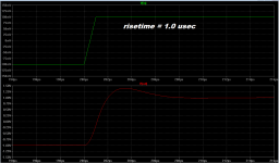
When there's a peak like this in the frequency domain, we expect overshoot in the time domain. (How much overshoot? Cordell's Figure 4.10 on page 91 shows a very nice nomogram). Sure enough, the square wave response does include overshoot -- see second and third plots*. Notice the rather leisurely 1 usec input risetime, much much slower than the upper limit of the rather zippy THAT preamp chip (22 MHz bandwidth!).
I used the diyAudio search engine and I also tried Google, to search for measured oscillograms of the Modulus-86's square wave performace. But I couldn't find a single one. If readers have an actual scope photo of a Modulus-86 square wave response, please post a link. It'd be fun to see how closely this simplistic little poles-and-zeroes linear systems model, predicts the real hardware's behavior.
* and sure enough, they agree with Cordell's figure.
Attachments
Last edited:
It can go to well beyond 180 degrees without problem IF this happens well away from (-1,0)So if the phase at 1kHz is 178.5degrees it is OK. I think we are all agreed.
If it changes to 179degrees, is it still OK?
If it changes to 179.5degreees, is it still OK?
If it changes to 179.9degrees, is it still OK?
How close can that dip get to 180degrees and that we can guarantee that it never exceeds 179.9degrees?
There must be tolerances in component values and device parameters.
There must be variations in loading reactances. Even the output Zobel components will have tolerances.
I show this exactly this in a post somewhere but I can't find it.
It's whether Bode's Return Ratio encircles (-1,0). LTspice has a Nyquist Plot that allows you to investigate this.
The horny handed mechanicals do this. That's why they are usually do with stability better than us mere electricians. 🙂Mark wrote:He is concerned about how close his simulation gets to 180degrees and Mark knows a lot more than me.
almost no one posts simulation predictions using this format
Have a look at :
http://www.diyaudio.com/forums/solid-state/268978-my-first-amplifier-design-6.html#post4222003
http://www.diyaudio.com/forums/solid-state/235188-tpc-vs-tmc-vs-pure-cherry-42.html#post3734089
and the discussions near these posts.
I used the diyAudio search engine and I also tried Google, to search for measured oscillograms of the Modulus-86's square wave performace. But I couldn't find a single one. If readers have an actual scope photo of a Modulus-86 square wave response, please post a link.
See post #30
Thanks for linking me back to those discussions.It can go to well beyond 180 degrees without problem IF this happens well away from (-1,0)
I show this exactly this in a post somewhere but I can't find it.
The horny handed mechanicals do this. That's why they are usually do with stability better than us mere electricians. 🙂
Have a look at :
http://www.diyaudio.com/forums/solid-state/268978-my-first-amplifier-design-6.html#post4222003
http://www.diyaudio.com/forums/solid-state/235188-tpc-vs-tmc-vs-pure-cherry-42.html#post3734089
and the discussions near these posts.
It seems that there are too many gaps in my knowledge to enable this to sink in and stay with me.
Thank you! I was searching for variations on the words square wave, which post #30 does not contain.See post #30
See post #30
Note that those transient response plots are of the MOD86 R1.0. The transient response of MOD86 R2.0 cleaned that up considerably. R2.0 will drive over 1 uF || 8 ohm with minimal ringing. At more reasonable values of load capacitance, there's no ringing at all on the response. I'll see if I can dig out the scope shots.
Tom
Last edited:
tomchr, any chance you would be doing a current-driver version of your amplifier?
The "current source" amps out there intended for driving speakers are actually rather poor current sources. They tend to have low output impedance. This is great for a voltage source (ideal Zout = 0) but not so useful for a current source (ideal Zout = infinite).
The issues surrounding Howland Current pumps, which applies to the current crop of "current source" amps, is covered quite well by Bob Pease in his white paper: http://www.ti.com/lit/an/snoa474a/snoa474a.pdf I suggest that anyone interested in building these "current source" amps, study that white paper first.
Tom
Thank you for your response.The "current source" amps out there intended for driving speakers are actually rather poor current sources. They tend to have low output impedance. This is great for a voltage source (ideal Zout = 0) but not so useful for a current source (ideal Zout = infinite).
The issues surrounding Howland Current pumps, which applies to the current crop of "current source" amps, is covered quite well by Bob Pease in his white paper: http://www.ti.com/lit/an/snoa474a/snoa474a.pdf I suggest that anyone interested in building these "current source" amps, study that white paper first.
Tom
I know nothing about the limits of current current-drive designs, nor I have the knowledge to understand these limits and the paper you pointed me to. But I had the opportunity to test what current drive could do in term of distortion reduction with a midbass driver (active EQ and filters, so no problem with compensating response variation as long as we stay above Fs), and I would love to be able to achieve this without dropping ahuge amount of what into an inline resistor...
So, I figures I should ask you as your designs look clever and efficient, and the chip you are using is often used in current drive amplifiers 🙂
I actually joined this thread in the hope of pearls of wisdom to build a current source amp for measurement up to a few Amps output.So, I figures I should ask you as your designs look clever and efficient, and the chip you are using is often used in current drive amplifiers 🙂
It's quite easy to get Zo 1k or more below 1kHz.
Alas, all these chip amps need a fairly drastic Zobel on the output which makes Zo much less at 20kHz.
But an amp for listening (as opposed to measuring) doesn't really need Zo zillion Ohms at 20kHz. Maybe a crude attempt is good enough.
But to get a few pp zillion THD like Tom needs a LOT of know how, gear and loadsa work on layout, earthing & decoupling.
Zobels are quite interesting. Before reading Toms web page, I sort of did not really consider the type of Zobel used in the Lm3886 data sheet; but after trying it, it does seem to provide a smoother high frequency signature with some improved clarity. It would be interesting to see how the second Zobel and the inductor resistor pair will effect the sound quality with short leads to the driver.
Sent from my iPad using Tapatalk
Sent from my iPad using Tapatalk
If you are comparing LM3886 with and w/o Zobel, the version without is almost certainly marginally unstable with load and will exhibit bursts on parts of the waveform depending on thermal & signal history bla bla. 😱Before reading Toms web page, I sort of did not really consider the type of Zobel used in the Lm3886 data sheet; but after trying it, it does seem to provide a smoother high frequency signature with some improved clarity.
No wonder so many Golden Pinnae amps sound different and are fussy about load. 🙂
Actually Zobels are most useful when they are as close to the Output Devices as possible.Best results when they are mounted/connected directly across the driver terminals.
Bob Cordel prefers distributed Zobels AT individual Output Devices for a big amp.
Zobels at the speaker address a completely different phenomena to do with significant Output Zo. Partial 'current drive' amps like Soong's or resistance/inductance in the speaker cables, will see large differences with a Zobel at the speaker.
- Home
- Vendor's Bazaar
- Modulus-86: Composite amplifier achieving <0.0004 % THD+N.