BTW, speakers likely to have a double digit distortion figure right? So listening to a system as a whole...
Not quite. Well, double digits in dB, that'll work ... -40dB on the low end with -50 to -60 dB over the rest of the course is quite doable with dynamic drivers. (1 to 0.1 % THD).
Member
Joined 2006
Is higher damping in the higher audible range really that important for reduced audible distortion? Once you get to a reasonably high damping factor, the main limiting factor is in cabling and voice coil resistance.
This can be tested easily enough with a small resistance in series with the tweeter. I've seen schematics of "good" speaker crossovers with just a series resistor to lower tweeter sensitivity to match other drivers (not even an L pad), so I'm doubtful high damping factor in that frequency range is critical.
Ben you are right in that above a certain number, Linkwitz uses 20, damping factor is not really important for loudspeaker performance. And many drivers are actually better with current drive. I posted some measurements of a small tweeter some time ago on this site. It is just that I consider a high damping factor as an important indication of the ability of an amplifier to faithfully reproduce its input.
Awesome! Thanks for the link.
Tom
4ohms ribbons are substantially resistive as an audio load.Well my numbers look ok, but I am borderline on current capability with my 3ohm ribbons. If you run the numbers a la cordell I am suboptimal on current. It's possible at least in a larger room than I am currently in that I could run out of headroom on peaks. Unlikely in current listening room though. And yes serves me right for not waiting for the parallel86.
But this is an edge case on an edge case 🙂.
They generally (I don't know your ribbons) draw the same transient currents as a resistive load would.
Thus we can assume that a 3ohms ribbon speaker will draw a similar transient current as an 8ohms speaker.
Where did you get that? 😕Thus we can assume that a 3ohms ribbon speaker will draw a similar transient current as an 8ohms speaker.
A 3R ribbon would be more like a 4 ohm nominal speaker.
A 4ohms speaker draws transients currents on fast stopping, or fast starting, signals that often approach 3times the current that a 4r resistor load would draw, i.e. expect a 1r3 resistor to demand similar transient currents as a 4ohms speaker when the signal is fast changing.Where did you get that? 😕
A 3R ribbon would be more like a 4 ohm nominal speaker.
In exceptional circumstances that ratio of speaker current draw to resistor current draw can exceed 5 times.
A 3r resistor would draw the same transient current as a 9ohms speaker if we set ourselves a 3:1 ratio for the relatively "often" that we are prepared to accept to avoid current limiting.
Where did you find this remarkable behaviour?A 4ohms speaker draws transients currents on fast stopping, or fast starting, signals that often approach 3times the current that a 4r resistor load would draw, i.e. expect a 1r3 resistor to demand similar transient currents as a 4ohms speaker when the signal is fast changing.
In exceptional circumstances that ratio of speaker current draw to resistor current draw can exceed 5 times.
A 3r resistor would draw the same transient current as a 9ohms speaker if we set ourselves a 3:1 ratio for the relatively "often" that we are prepared to accept to avoid current limiting.
I was a speaker man for most of my previous life and have investigated this in detail. I found no evidence of what you describe. You can forget the rubbish from the false prophet Otala.
In fact, there is ONLY one circumstance where a moving coil speaker would draw more current than you'd expect from its impedance curve. In that singular event, you certainly don't want your amp to provide a zillion amps.
Alas, speakers ARE (very) time-variant. 😡Wouldn't that imply that the load is either reactive or time-variant?
It's only convenient for us to pretend they are Linear Time Invariant. 🙂
Inspection of any impedance curve will also show they are quite reactive too.
A 4ohms speaker draws transients currents on fast stopping, or fast starting, signals that often approach 3times the current that a 4r resistor load would draw, i.e. expect a 1r3 resistor to demand similar transient currents as a 4ohms speaker when the signal is fast changing.
In exceptional circumstances that ratio of speaker current draw to resistor current draw can exceed 5 times.
A 3r resistor would draw the same transient current as a 9ohms speaker if we set ourselves a 3:1 ratio for the relatively "often" that we are prepared to accept to avoid current limiting.
I have never, NEVER, witnessed a driver where the impedance goes below Re. And I have been doing driver impedance measurements since the eighties.
I do not have the capability at the moment to accurately measure impedance of the ribbon over frequency. All I have is the impedance plot of the unmolested speaker with crossover courtesy of Stereophile, which allows a little inference but not much. Sadly I don't seem to be able to attach today due to some network problems on this end.
Speakers are typically reactive, so the current lags the voltage. This means that when the output voltage passes through zero, Iout will be nonzero. And ohms law says R=Vload/Iload, so at that exact moment the speaker load is zero ohms. Are you going to argue with ohms law now? 😉I have never, NEVER, witnessed a driver where the impedance goes below Re. And I have been doing driver impedance measurements since the eighties.
(Yes, I'm aware this reasoning is hopelessly incorrect. But just watch now, someone will run with it and use it as a justification for needing a massive damping factor, 4 gauge speaker wire, and who knows what else...)
I have never, NEVER, witnessed a driver where the impedance goes below Re. And I have been doing driver impedance measurements since the eighties.
Possibly this is a Kind of side effect during meassuring when not taking the counter magnetic effect into acount? When the mechanical reaction takes place the induced voltage might make the virtual R appear less then existent.
Err.rrh! How do you measure WITHOUT taking the 'counter magnetic effect into account'?Possibly this is a Kind of side effect during meassuring when not taking the counter magnetic effect into acount? When the mechanical reaction takes place the induced voltage might make the virtual R appear less then existent.
This is something that was of great interest to me in my previous life.
Anyone have evidence of this remarkable behaviour .. or a proper theoretical reason that it even happens?
I've already mentioned one bit of theoretical liquid BS from Otala. (which is sorta related to gmarsh's example. 😀
Last edited:
The report is linked in a Thread on this Forum.
It is an effect that has been written about many times.
It is an effect that both D.Self and R.Cordell have written about.
The extra current draw of a two way speaker, relative to a resistor load, is well documented.
It is an effect that has been written about many times.
It is an effect that both D.Self and R.Cordell have written about.
The extra current draw of a two way speaker, relative to a resistor load, is well documented.
Possibly this is a Kind of side effect during meassuring when not taking the counter magnetic effect into acount? When the mechanical reaction takes place the induced voltage might make the virtual R appear less then existent.
Nope, never seen it. The reason some speaker systems have such low impedances is not the way the drivers behave, but the xovers they are mounted to, especially if they use elliptical filters.
Let's not use too much bandwidth on Tom's thread to discuss speakers.
Last edited:
The extra current draw of a two way speaker, relative to a resistor load, is well documented.
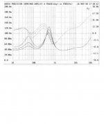
So apples and eggs? I can attach again so here is the impedance plot of the original with crossover. You can see it gets a bit reactive at high frequencies, but naff all energy up there. All meaningless until I can measure the ribbon in isolation tho.
Attachments
continuous sinewave test signals do not show the effect that I was referring to
Unfortunately I can't interpret your graphs. I don't know what the vertical scales are telling me. There is certainly a slope from 2.5kHz to 20kHz.
I also don't know what how to separate out the crossover from the ribbon tweeter to see how reactive the ribbon is, or is not.
Maybe some of the speaker experts can interpret for you.
ESP also discusses this.transients currents on fast stopping, or fast starting, signals
Unfortunately I can't interpret your graphs. I don't know what the vertical scales are telling me. There is certainly a slope from 2.5kHz to 20kHz.
I also don't know what how to separate out the crossover from the ribbon tweeter to see how reactive the ribbon is, or is not.
Maybe some of the speaker experts can interpret for you.
Last edited:
- Home
- Vendor's Bazaar
- Modulus-86: Composite amplifier achieving <0.0004 % THD+N.