Beautiful work Tom! I can't wait for the measurements since I'll be building an 8 channel version of the Parallel-86 in a 4U chassis for my theater.
;-)
Anand.
;-)
Anand.
Could you test the parallel-86 also in bridged mode
(so it could be used with XLR inputs )
I'm interested what max voltage supply level could be used incase 2 parallel -86 configured in bridge mode
I'm planning on it.
The Parallel-86 is the perfect circuit for a bridged amp. It is also a good candidate for those needing to drive low impedance speakers.
The maximum supply voltage depends on the load impedance. I recommend staying below 40 W dissipation in each half of the LM4780 (or LM3886 for that matter). This limits the supply voltage to the Parallel-86 to:
±35 V for 4-8 Ω load
±28 V for 2 Ω load
A bridged Parallel-86 would be limited to:
±35 V for 8 Ω load
±28 V for 4 Ω load
±20 V for 2 Ω load
A single Parallel-86 board should provide 160/130/65 W into 2/4/8 Ω.
A bridged Parallel-86 should provide 350/350/280 W into 2/4/8 Ω.
Above numbers are based on math and should hold up reasonably well in practice. The output powers at low impedance will probably be a bit lower than calculated.
Very nice. How much space is between V- and the heat sink side of the board edge?
25 mil = 0.635 mm. I never run planes all the way to the edge of the board. Bad things happen when you do that...
Hey hey hey!! Congrats on the new arrival! Very exciting.
I have to finish building my second helping before I come back for thirds, but I am planning on it.
Awesome. Thank you! Yeah... A lot of people seem to be in building mode. That's good to see.
~Tom
Tom, et al.
A little lightbulb went off in my head yesterday, about input voltage limit. I had always envisioned it as a limiter function, brick wall, nothing over 1.75V gets past. But the lightbulb has me thinking that couldn't true. Kinda like the mythical clunk when you switch from class A to class AB.
Is there actually a (numerical value constant) limit to input voltage beyond which the input stage will not accept higher voltage? Or is the input voltage spec really just an arbitrary voltage that describes when the amp makes max power at a given load?
So that if the load is easier, the input voltage limit would rise, and if harder load would drop?
Thanks for clarifying!
THAT1200 specsheet:
"Input Voltage Common mode ±13.0V, Differential (equal and opposite swing) 21.5 dBu"
This input stage will not clip with signal from any consumer level sources. I initially used a semi-pro audio interface (Prosonus Firepod) which was much louder signal than consumer preamp I use now and it did not clip the Modulus.
I've heard the static-like transient snapping sound Spike protection but I have never heard any voltage clipping.
I had always envisioned it as a limiter function, brick wall, nothing over 1.75V gets past.
The input sensitivity is really just the input voltage that is required to get the specified output power. At least that's my interpretation.
38 W into 8 Ω is 17.44 V RMS. The gain of the Modulus-86 R2.0 is 10 V/V, so the input sensitivity is 17.44/10 = 1.744 V RMS.
On a ±28 V supply I'm usually able to get a tad beyond 38 W and find 1.75 V is where the amp is just a hair below clipping. So I rounded 1.744 up to 1.75 on the spec sheet.
The only "brick wall" limiter is the power supply. Once the LM3886 hits the rails, the output amplitude will not increase further. This is known as clipping as is generally to be avoided. 🙂
I did consider implementing a limiter to prevent the amp from clipping, but decided against it as clippers tend to activate too early and cause distortion. A clipper would also have to track the power supply as the amp will clip a lot earlier on 20 V rails than on 28 V rails...
Is there actually a (numerical value constant) limit to input voltage beyond which the input stage will not accept higher voltage?
You've found the limit for the THAT1200. You'd then need to ensure that the output of the THAT stays within the allowed input range of the LME49710 and LM3886 (hint: it does).
Or is the input voltage spec really just an arbitrary voltage that describes when the amp makes max power at a given load?
I'm half guessing that if an amp is THX certified, its input sensitivity will be 2 V RMS for 100 W out even if the amp is a 1 kW amp. That's just my guess.
~Tom
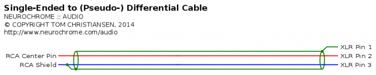
To connect unbalanced source to amp,
Connec/bridge Gnd and in- ???
That's one way. You'll get better performance if you use a pseudo-differential interconnect cable between your signal source and the MOD86.
~Tom
Attachments
A few measurements from the Parallel-86
I managed to squeeze in a few measurements this morning.
±35 V supply. 8 Ω load. Max output power: 64 W (0.00045 % THD+N).
±35 V supply. 4 Ω load. Max output power: 120 W (0.00055 % THD+N).
±28 V supply. 2 Ω load. Max output power: 127 W (0.00079 % THD+N).
All measurements were taken at 1 kHz with 22 kHz bandwidth. The THD profile looks very similar to that of the Modulus-86 (as expected) with the obvious exception of the higher output current capability. The THD+N measurement above for 2 Ω load may be limited by the power supply.
These measurements are still preliminary results. I need to optimize the measurement setup to ensure that the amp is measured at the sweet spot of the APx525. I'm pushing the capabilities of the APx525 to the edge here... Once I have the setup fully optimized, I expect to get slightly better THD+N.
I'm booked the rest of today and tomorrow. I should be able to start pushing the amp through its paces around the middle of the upcoming week.
So far so good, though...
~Tom
Last edited:
Tom,
What speakers do you use to verify that the excellence of the specification / measurements match with a marvellous sound?
What speakers do you use to verify that the excellence of the specification / measurements match with a marvellous sound?
Dali 3A
Alpair 6P
Besides, the correlation between good measurements and good sound quality is well-documented by Harman Kardon. You can find links to the study elsewhere in this thread as well as on Sean Olive's blog.
~Tom
Alpair 6P
Besides, the correlation between good measurements and good sound quality is well-documented by Harman Kardon. You can find links to the study elsewhere in this thread as well as on Sean Olive's blog.
~Tom
Well, the Hypex nc400 measured very well (with "tons" of negative feedback to achieve this) but not everyone likes, especially for HF / tweeter.
An externally hosted image should be here but it was not working when we last tested it.
Yesterday I decided that your design is what better approaching my needs (I have lots of noise, DC and fluctuations of voltage in the mains).
I have created a thread (in Spanish) where I am going to keep track of the process.
Parallel-86, amplificador con chipamp LM4780 más op-amp LME49710 y OPA2277, diseñado por Tom Christiansen
First I want to make sure that others verify sound quality!
I have created a thread (in Spanish) where I am going to keep track of the process.
Parallel-86, amplificador con chipamp LM4780 más op-amp LME49710 y OPA2277, diseñado por Tom Christiansen
First I want to make sure that others verify sound quality!
Last edited:
The "scientific types" 😀 hold that the measurements that they do are "good enough", if something falls outside the realm of what they capture with instrumentation then it is largely irrelevant, 😛.
Generally takes someone with a fresh approach, ie. younger 😉, to advance the status quo ...
Generally takes someone with a fresh approach, ie. younger 😉, to advance the status quo ...
Yes, definitely "old", 😀 ... non-scientific, definitely not. I'm against the "Blinding You With Science!" routine - I'm all about Appropriate Science, that is, actually measuring what is going to be relevant, most crucial - rather than, I've got this you beaut bit of expensive equipment which can pump out reams out of impressive looking numbers, and very spiffy graphs - which, hopefully, will tell one something that is useful.
I am very impressed by Tom's efforts, this kit looks remarkably good, hence my keeping an eye on it - the real point is, how come different examples of finished circuits that "measure brilliantly" evoke different reactions from the people listening - how far do you want to push the "It's all in your head! You've got a thing against this type of solution!" sort of thing as an explanation for everything that doesn't fit?
I am very impressed by Tom's efforts, this kit looks remarkably good, hence my keeping an eye on it - the real point is, how come different examples of finished circuits that "measure brilliantly" evoke different reactions from the people listening - how far do you want to push the "It's all in your head! You've got a thing against this type of solution!" sort of thing as an explanation for everything that doesn't fit?
Last edited:
The day you post a coherent measurement I will see a platoon of pigs fly past the window.
In your case it is all inside your head.
In your case it is all inside your head.
Coherent? The word to use is "relevant", actually ... my interest is in what makes something "sound good", that nebulous aspect of a final creation that everyone throws around as a final word on this forum, about their designs ... that's the only thing that matters! And no-one can "measure" it, as yet, 🙂.
One can measure various dimensions of a creation at the moment, which contribute to it "sounding good", but not what the latter actually is! This is the guts of the whole audio thing - otherwise, if it fails this test it gets thrown into the junk pile, end of story.
If I think I've truly measured, with an instrument, something meaningful I'll certainly post it. In the meantime my ears are telling me all I need to know - and of course they don't count ... 😉.
The "scientific types" 😀 hold that the measurements that they do are "good enough", if something falls outside the realm of what they capture with instrumentation then it is largely irrelevant, 😛.
I aim to design circuits that perform well. As documented elsewhere, there is significant correlation between "measures well" and "sounds good". The main issue seems to be that some people take one measurement and try to conclude the world from it. You have to see many measurements in context to conclude anything meaningful about the performance of an amp. That's where I come in...
I would also argue that those who claim that the "scientific types" are missing something tend to miss the whole science called psychology. Specifically, human perception and cognition.
~Tom
Yes, "many measurements in context" is what's crucial ...
The abilities of human perception tend to be not given much credence by many in audio, ignoring the fact that people can learn to distinguish fine qualities in sound if they choose to do so - the supposed ability of musicians, and conductors of orchestras to "hear" subtle problems in a wash of sound is a complete nonsense otherwise.
The abilities of human perception tend to be not given much credence by many in audio, ignoring the fact that people can learn to distinguish fine qualities in sound if they choose to do so - the supposed ability of musicians, and conductors of orchestras to "hear" subtle problems in a wash of sound is a complete nonsense otherwise.
- Home
- Vendor's Bazaar
- Modulus-86: Composite amplifier achieving <0.0004 % THD+N.